Via Inspector
Introduction
Via Inspector is a dialogue based analysis tool for the vias currently in use on the board. It can be used in two ways:
- To check which vias and drill hole sizes are in use for which drill ranges and whether they have been filled, tented or depleted.
- To make bulk changes to vias on the board.
The inspector shows both standard (CNC drilled) vias and micro-vias (laser drilled). Filters allow you to isolate one type or the other, and the action buttons operate on the selected vias according to their type.
To open Via Inspector
- Switch to via mode.
- Click on the via inspector icon above the parts bin.
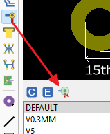
The via inspector button above the parts bin in via mode.
Or launch from the command on the Tools Menu.
If this is a tool you will use frequently you can map it to a keyboard shortcut from the System Menu > Set Keyboard Mapping command.
The Dialogue Form
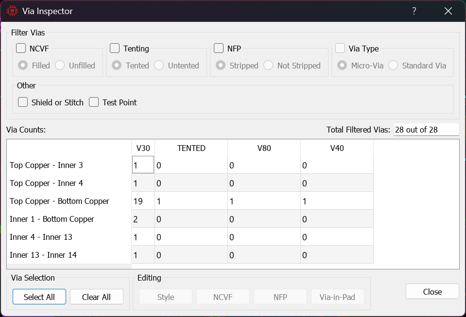
The Via Inspector Dialogue Form
The dialogue is split into three main sections: filters, data table and action buttons.
Filters
The filter section at the top of the dialogue restricts which vias appear in the data table. With no filters enabled, all vias on the board are shown. There are six filters available:
NCVF
Filters by the filled status of each via. When enabled, the data table can be restricted to show either only filled or only unfilled vias. The filter operates on the underlying filled flag, so it shows all vias that are marked as filled: this includes both resin filled through-hole vias (CNC drilled, filled with non-conductive epoxy) and micro-vias (laser drilled, filled by copper electroplating as part of HDI fabrication).
Filled vias of a particular style are also shown as a separate column in the data table. For example, if you had some filled vias of style V20 then you would see a column for V20 and a column for Filled V20.
See Also:
NFP
Filters by non-functional pad status. A via with NFP has its annular ring removed on layers where there is no electrical connection (the extremities always retain their rings). This filter can show only depleted vias or only intact vias.
See Also:
Tenting
Filters by tenting status. A tented via has no solder mask (guard gap) opening, meaning the solder resist will cover the annular ring and barrel. This filter can show only tented or only untented vias.
See Also:
Via Type
Filters by via type. When enabled, the data table can be restricted to show either only micro-vias (laser drilled, HDI) or only standard vias (CNC drilled). This is useful on HDI boards where both via types are present and you need to inspect or edit one category independently. On boards without an HDI stackup (i.e. no micro-via drill spans defined), this filter group is disabled.
A via is classified as a micro-via based on its via style having the micro-via flag set. The filter does not examine drill span; it checks the style flag only.
Shield or Stitch
When enabled, restricts the data table to vias that were auto-placed by the stitching or shielding dialogue forms. These are vias owned by a zone object. Manually placed vias are excluded.
See Also:
Stitching & Shielding Zones with Vias
Test Point
When enabled, restricts the data table to vias that have been designated as testpoints.
See Also:
Data Table
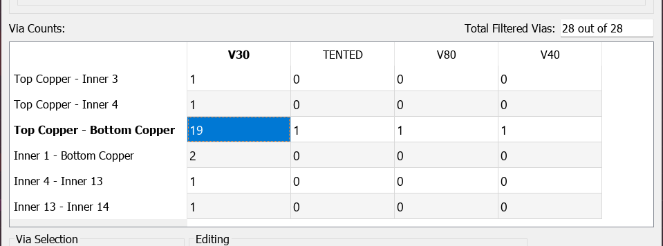
The data table shows how many vias of each style and layer range are placed on the board.
The data table summarises the vias on the board according to the active filters. Each row represents a drill range (as specified in the layer stackup) and each column represents a via style. Where some vias of a style are filled and others are not, they appear in separate columns; the filled group has "Filled" prefixed to the style name.
Click on one or more table cells to highlight those vias on the board. Click on a row header to select all vias in that drill range, or a column header to select all vias of that style. The editing window zooms to show the selected vias.
All drill ranges defined in the layer stackup are shown as rows in the table, even if no vias currently use that range. This gives a complete view of the available drill spans.
Action Buttons

The action buttons allow you to make bulk changes to the placed vias.
The Select All and Clear All buttons control the table selection. The remaining four buttons perform editing operations on the selected vias:
Style
Changes the via style for all selected vias. The procedure is to create a new via style (appropriately named) with the characteristics you want, then select the vias in question and change to that new style from this button. This button is enabled whenever any vias are selected in the data table.
Use with caution. You are making a bulk edit on your PCB. Changes to annular ring or drill hole sizes will often result in a mass of DRC errors.
If you change vias to a micro-via style, the software checks that each via's drill span is compatible with a lasered span. Vias with incompatible spans are skipped and a warning message shows the count of skipped vias.
NCVF
Sets or unsets the filled flag on the selected vias. This button opens the Non-Conductive Via Fill dialogue, which offers two actions: set vias as resin filled, or unset via filling.
This button is only enabled when plated through-hole (PTH) vias are selected in the data table. It does not operate on micro-vias, because micro-vias are always filled as part of HDI fabrication and this cannot be changed. It also does not operate on blind or buried vias.
The term NCVF (non-conductive via filling) refers to the resin filling process used for CNC drilled through-hole vias. Micro-vias use a different process (copper electroplating) but share the same filled flag internally. Both types are output as IPC-4761 Type VII in Gerber X2.
For more control, you can fill vias individually through the right click context menu or by dragging a selection box and then using the context menu command to fill.
NFP
Removes or restores non-functional pads (unused annular rings) on the selected vias. Annular rings are always maintained on the two extremities of each via. This button is enabled whenever any vias are selected in the data table.
As with filling, non-functional pad removal can also be done individually or by selection box using the context menu.
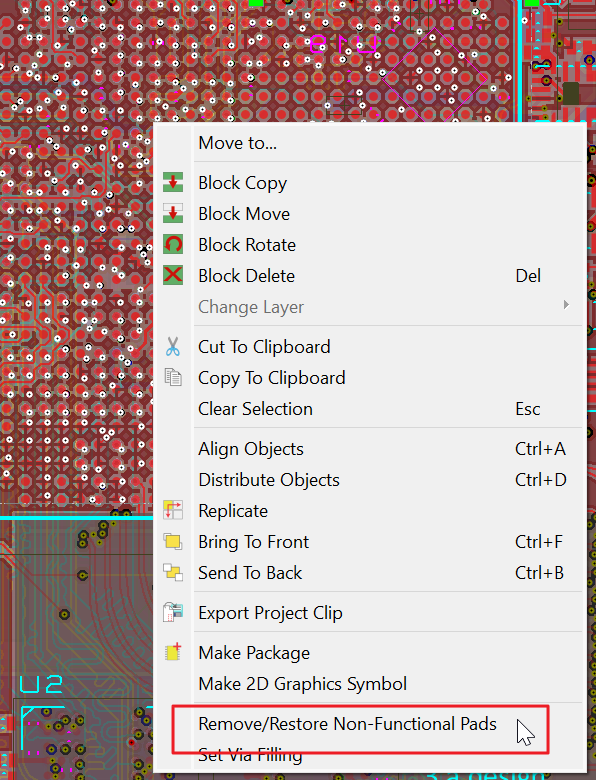
Removing non-functional pads from a single via using the right click context menu.
Via-in-Pad
Sets or unsets the filled flag specifically for vias that geometrically intersect a component pad. This is the bulk equivalent of the per-via filling option but targeted at via-in-pad configurations, typically vias placed directly in BGA pads.
When invoked from the Via Inspector, the operation applies only to the vias selected in the data table. For each selected via, the software checks whether a component pad exists at the same position on overlapping layers. Only vias that pass this geometric test are affected.
Like the NCVF button, this button is only enabled when plated through-hole vias are selected. It does not operate on micro-vias (which are always filled) or on blind and buried vias.
Both the NCVF and Via-in-Pad buttons set the same underlying filled flag. The difference is scope: NCVF operates on all selected PTH vias, while Via-in-Pad operates only on the subset that intersect component pads.
Micro-Vias in the Via Inspector
The Via Inspector displays both standard and micro-vias in the same data table. On HDI boards where both types are present, the following points are relevant:
- Use the Via Type filter to isolate micro-vias or standard vias for inspection.
- Micro-vias appear on lasered drill span rows in the data table (e.g. Top Copper - Inner 1). Standard vias appear on CNC drilled spans.
- Micro-vias are always marked as filled. They will appear in the NCVF "Filled" filter results and in "Filled" columns in the data table.
- The NCVF and Via-in-Pad action buttons are disabled for micro-vias. To change a micro-via property, use the Style button to change the via style.
- The NFP button can operate on micro-vias (removing unused annular rings on inner layers).
Examples
To check all testpoint vias on the board
- Launch via inspector from the object selector in via mode.
- Select the testpoint checkbox to restrict the data table to testpoint vias.
- Click on any cell entry in the table to highlight the vias on the layout.
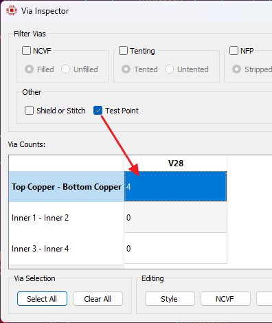
The data table filtered to show only testpoint vias.
To find all untented vias on the board
- Launch via inspector from the object selector in via mode or the tools menu.
- Select the tenting filter and make sure the radio button is set to untented.
- Click on any cells of interest in the resulting data table to highlight on the board.
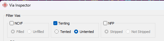
The tenting filter set to untented, listing the untented vias on the board.
To tent all the through-hole V20 vias on the board
- Create a new via style and call it V20T or V20Tented or similar.
- Set the guard gap to be not present on the via style. This means no solder mask opening for the via.
- Launch via inspector.
- Click on the data table cell entry for V20 vias from top copper to bottom copper. Double check!
- Click the style action button at the bottom and change the style to V20T.
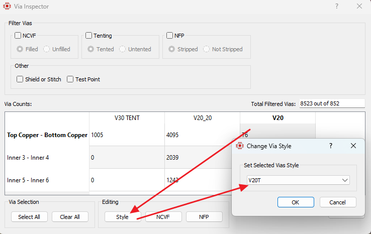
Changing the selected top to bottom copper V20 vias to the tented V20T style.
See Also: