HIGH SPEED ROUTING EXAMPLES
Introduction
The examples below cover a range of common routing tasks on high speed signals or nets in Proteus. In all cases it is assumed that the board has been set up with the basics. This means:
- The basic design rules from the Design Rule Manager and that you have a basic understanding of Net Classes.
- A layer stackup and drill spans have been thought about and defined.
- Layer pairs have been configured as required.
- The Set Length Tuning dialogue has been configured as required.
Length matching and net tuning are part of the Advanced Feature Set, available from PCB Level 2 onwards.
The commands used throughout these examples live in the High Speed Design submenu of the track context menu: Match route lengths, Input target length, Remove length matching, Tag length matches, Reverse route direction and Configure length matching.
Example: Matching the Lengths of two Routes
To match the lengths of two routes:
1) Configure the length tuning as required with the Technology Menu > Configure Length Matching command.
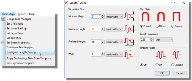
Configure the serpentine size, cap style and tolerance before matching.
2) Enter selection mode and left click to select one of the routes.
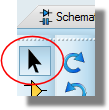
Selection mode on the modes toolbar.
3) Hold the CTRL button down on the keyboard and left click on the second route. You will then have both routes highlighted.
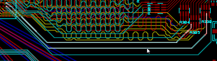
Both routes highlighted ready for matching.
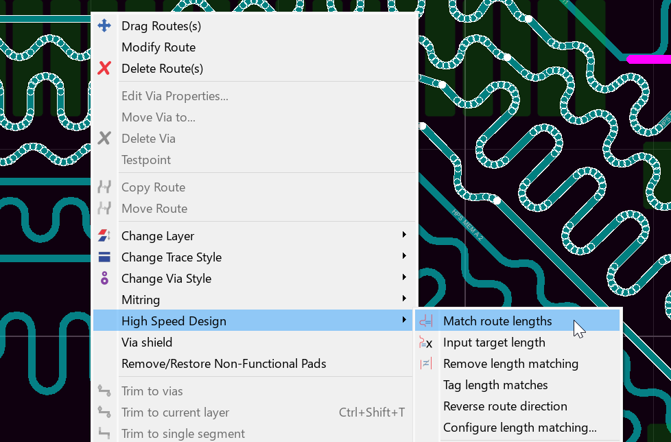
4) Right click on either one of the routes and select High Speed Design > Match route lengths from the resulting context menu.
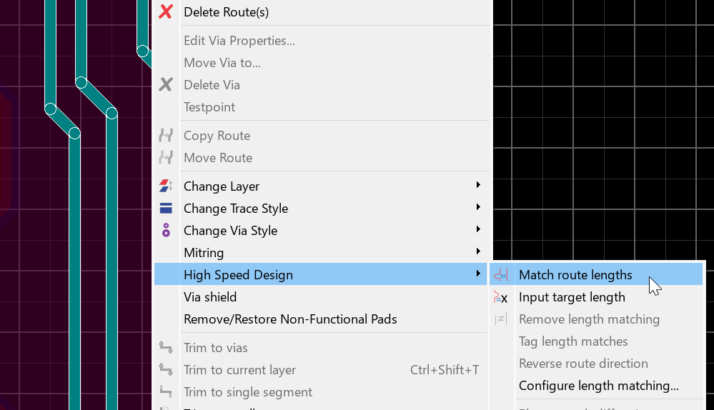
Match route lengths on the High Speed Design submenu.
You can use this matching technique with as many tagged routes as you like. However, if you have a lot of routes close together (e.g. a bus) that you want to match it can be tricky for the software to automatically find the space to match all the routes in one operation. With a large bus therefore, you would tend to match a few routes, move the serpentines sections manually to create some space, then add a few more routes.
The Tag Track Connections command on the Tools Menu is really helpful here and will select all connections between two components. In the case of a bus you may even be able to select and match them all directly.
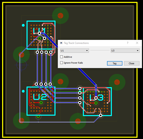
Tag Track Connections selecting routes between U1 and U3. CTRL+click on a segment can de-select as well as select.
See Also:
Adding Routes to an Existing Matchgroup
Moving a Serpentine on a Route
If you select a track that has been length matched you will find that both the route length and also the target length are shown in the status bar.

The status bar shows the route length and the target length for the matchgroup.
Example: Setting the Length of a Single Route
To set the length of a particular route:
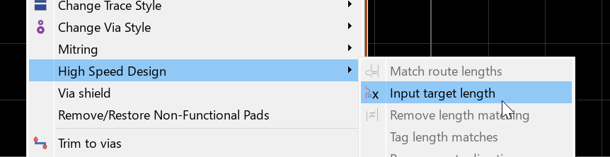
1) Right click on the route and select High Speed Design > Input target length.
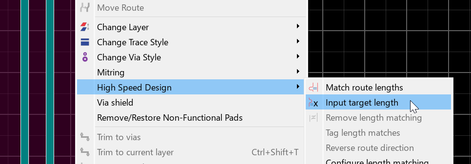
Input target length on the High Speed Design submenu.
2) Type in the target length along with unit suffix (mm, th, etc.). Obviously, the entered value must be larger than the current length of the route.
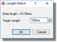
Enter the target length with its unit suffix.
If you have set Uniform Height to Centred or On this operation will fail a significant portion of the time unless you have an extremely high tolerance. This is because the difference in lengths is unlikely to be an exact number of serpentines, which is what would be required if the serpentines are not allowed to change size. We strongly recommend therefore that you allow irregular serpentines by setting Uniform Height to Off before attempting an absolute length set operation.
Example: Moving a Serpentine on a Route
You can move or position the serpentine section on the route as follows:
1) Select the route by left clicking on it.
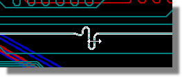
2) Drag and drop with the left mouse. So, left depress the mouse over the serpentine section, drag to the desired location and release the mouse to drop in it's new location.
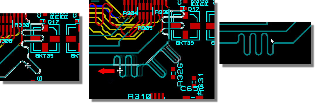
Drag the serpentine section to a different place on the route.
Troubleshooting
If a serpentine will not drag it is almost always because the design rules do not allow it to move. The classic example is shown below.
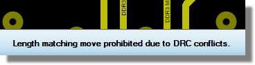
The lower serpentine rises above the base line of the upper track and blocks it.
The upper serpentine cannot be dragged because the serpentine on the lower track is higher than the base line of the track (where the track would run if there was no wiggles). Any movement on the serpentine will result in a DRC error and therefore blocked. The solution is simply to first move the lower serpentine such that the one on the upper route is clear (e.g. having them perfectly out of phase).
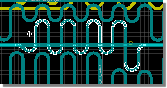
Move the lower serpentine clear of the upper route to unblock it.
Note also when dealing with complex length matching that you cannot move a serpentine onto a segment of track that is shared between two or more matchgroups (because it would change the length of all of the routes).
Example: Adding Routes to an Existing Matchgroup
It is quite common to want to length match a large number of routes and it can be tricky to do so in a single operation. The best way to length match multiple tracks is in several stages, allowing you to move serpentine lengths to maximise free space at each stage.
1) Length match the first few tracks.
Length match the first few tracks.
2) Move the serpentines to make as much space as possible for serpentines in the next route.
Move the serpentines to free up space for the next routes.
3) Select one of the existing length matched routes and a couple more that you want to be matched and then length match again.
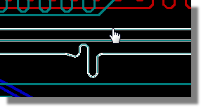
Include one already matched route in the next selection to join the routes to the same matchgroup.
4) Repeat stages 2 and 3 as often as required.
See Also:
Moving a Serpentine on a Route
Example: Removing a Serpentine from a Route
To remove a length match (serpentine segment) from a route:
1) Right click on the route and select High Speed Design > Remove length matching from the context menu.
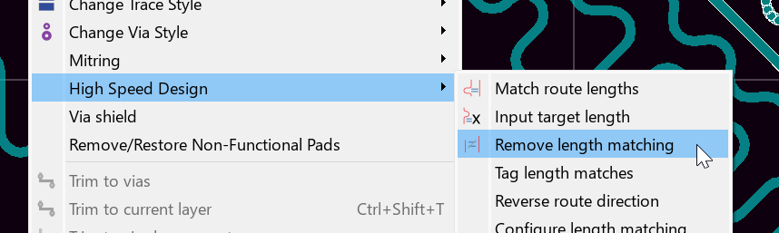
Remove length matching on the High Speed Design submenu.
This will restore the route to it's previous (original) etched copper length and remove it from the matchgroup that it belonged to. Also:
- If the routes in the matchgroup have been length matched against each other and you have removed the route with the longest original length then the matchgroup will be regenerated. All other routes will be matched to the length of the longest route remaining in the matchgroup.
- If the routes in the matchgroup were matched to a specific length (via the input target length command) then there will be no change to the other routes in the matchgroup.
- If the route is the last or only route in the matchgroup then the matchgroup will also be destroyed at this point.
Example: Selecting all Routes in the Same Matchgroup
To see all of the routes in the same matchgroup:
Either:
1) Right click on one of the tracks and select High Speed Design > Tag length matches.
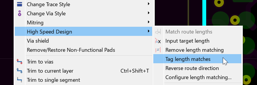
Tag length matches on the High Speed Design submenu.
Or
2) Generate a length match report in the Project Notes module, which is grouped by matchgroup.
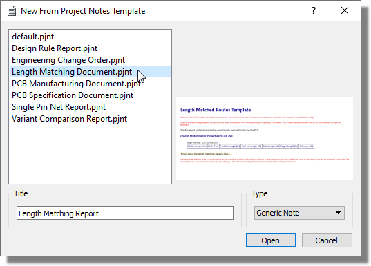
Select the length match template in Project Notes.
Or
3) Select connectivity highlights mode, change the Object Selector filter to Length Matched and then double click on one track in a matchgroup to select the entire matchgroup on the layout.
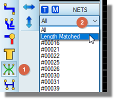
The Object Selector filtered to length matched routes.
See Also:
Producing a Length Match Report
Example: Length Matching with Fly-By Topology
First, apply internal lengths if required.
Next, find the route with the shortest length of common track and use the CTRL button with successive left clicks to select the entire route from source pin to destination pin. You can also use the Tag Track Connections command on the Tools Menu.
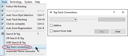
Quickly tag connections between components using the command on the Tools Menu.
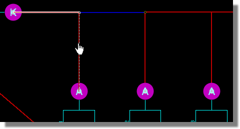
Or simply hold CTRL down and tag segments consecutively.
Right click and match to calculated length. Move the serpentine segment as required.
Match the first route, then position its serpentine.
Now hold CTRL button down and successively left click on each section to highlight the next route. Again, we are going from source pin all the way through to destination pin, including segments of track that may have been selected in our previous match.
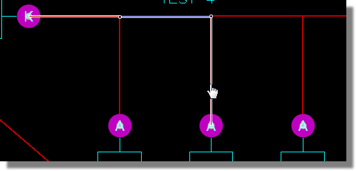
Tag the next route in full, including the shared segments.
Right click and match to calculated length.
Repeat as required with other routes.
Example: Adding Internal Lengths to the Calculations
First, get the required data from your manufacturer's software. If this is coming out as a delay you'll need to use the dielectric of the chip to translate into a distance.
Open a copy of notepad or similar and type a comma separated file of pin names and internal lengths. Save the file and then apply the internal lengths with the Add Internal Lengths command on the pad context menu. The example below is for a BGA:
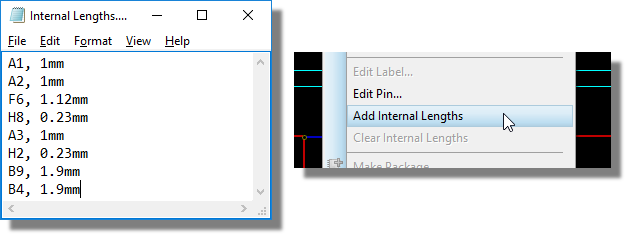
Internal lengths for a BGA as a comma separated list of pin name and length.
Example: Editing and Re-matching a Matchgroup
The good news here is that re-matching is automatic after an edit so, provided there is enough space on the layout, everything should just work. However, you still need to:
- Verify that everything has worked and is inside tolerance.
- Fix it if it hasn't.
So, let's assume we've had to nudge a memory IC a little and a bunch of routes from it are length matched. We need to assess the impact on the length matched tracks, so we filter the Object Selector to the length matched routes. Do this by selecting connectivity highlights and then setting the filter to Length Matched.
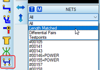
Set the Object Selector filter to Length Matched.
See Also:
Viewing and Browsing Matchgroups
Routes are grouped by matchgroup and the right hand side of the display shows the compliance of each length matched route to it's target (T). Hovering the mouse over the selected route will show you both the target distance and the tolerance in a tooltip. Assuming all is well therefore the right hand side should all be green.
If a route is non-compliant it will be in red and an indication provided of how badly it's outside of target distance. Double clicking on this will tag the route making it easier to adjust and the display will update live after each edit.

A non-compliant route is shown in red with the amount by which it misses the target.
It is possible, although unlikely, that no matching could take place at all after an edit which disturbs a matchgroup. This would create a situation where previously length matched routes are no longer length matched at all, and therefore no longer listed under the Length Matched filter. So, the first check should be that your matchgroups are all still listed after editing their lengths.
Example: Bus Length Tuning with a Strobe Reference
When routing memory interfaces such as DDR, all of the data lines in a byte lane (DQ) must be matched in length to their associated strobe (DQS).
In Proteus this is achieved by tuning the bus lines together so they all match the longest member of the group, which should normally be the DQS.
- Route the strobe (DQS) and the data lines (DQ0…DQ7) as usual.
- If the memory vendor specifies an internal package delay, enter it as an internal length on the appropriate pin and Proteus will include it automatically during matching. Internal lengths are automatically included in Proteus’s calculation of the effective net length. So if a Micron datasheet says “DQS to DQ package delay = 20 ps,” you’d model that in Proteus as an Internal Length of about 3 mm (about 120 mil), assuming 150 ps per inch.
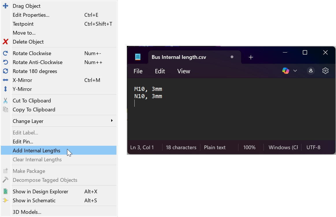
- Select the DQS net and all associated DQ nets in the layout. CTRL+left click to consecutively select routes.
- Right click and choose High Speed Design > Match route lengths.
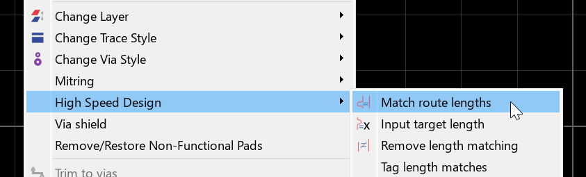
Proteus automatically calculates the length of each route and adds serpentine tuning to the shorter nets until they match the longest within the configured tolerance.
Use the Technology Menu > Configure Length Matching command to set the geometry of the tuning segments: minimum and maximum height, preferred style and tolerance.
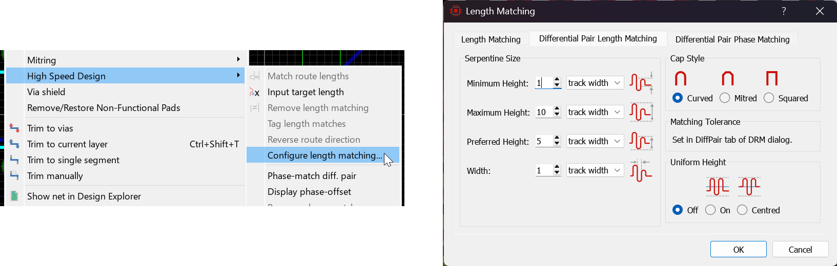
Set the serpentine geometry before tuning the bus.
Notes:
- If DQS is shorter than the DQ lines, it will be lengthened instead and the others left untouched.
- Tuning is always relative to the longest member of the selected set; there is no separate “reference net” concept.
- Where a vendor publishes an internal package delay rather than a length, convert it to a distance using the propagation figures below and enter the result as an internal length on the pin. Proteus then folds it into the matching automatically, so there is no need to adjust target lengths by hand.
Alternative Method: Absolute Length
In some cases a protocol or vendor specifies an absolute length requirement, for example “all DQ and DQS lines must be 1250 mil ±50 mil”.
- Select the nets to be tuned.
- Right click and choose High Speed Design > Input target length.
- Enter the required target length and tolerance.
- Proteus adds serpentine tuning until all selected nets fall within the specified window.
Notes:
- This method is less common for DDR but useful where a datasheet defines a fixed electrical length.
- Conversion between delay and length may be required. In FR-4, propagation delay is typically about 150 ps per inch (6 ps per mm) for surface microstrip traces, and 170–180 ps per inch (≈7 ps per mm) for internal striplines.
Example: Producing a Length Match Report
The length match report is created in the Project Notes module and contains information about each route including pin names, matched length together with tolerances and internal lengths. To generate a length match report:
1) Open the Project Notes module and select the length match report template.
Select the length match report template in Project Notes.
2) The report will auto-generate and can be saved out as a PDF file or stored with the Proteus project itself.

Save the report out as a PDF file or store it with the project.
3) You can regenerate the report after changes via the right click context menu command.
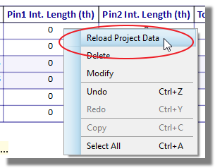
Regenerate the report from the right click context menu after making changes.
The length match table is known as a data object and can be inserted into any report you like. So, you can create your own report / corporate style and then insert data objects like this into it.
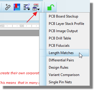
Insert the length match table into a report of your own.