BACK-ANNOTATION
Overview
Back annotation is the process whereby changes to the component annotation on the PCB can be fed back into the schematic. This would normally be done if it was felt that a particular order of annotation on the PCB would aid the production department in making the board. In fact, the most natural order for this purpose is if placement path for placing the components in successive order is a minimum.
There is no Back Annotate command to invoke. Back annotation happens by itself whenever you change the annotation on the layout, provided the layout holds a valid netlist and is not locked. Those two conditions are the whole of the story: if either fails, the change is simply not passed through, which is why re-annotating with live netlisting switched off leaves the layout locked until you confirm the netlist change yourself.
Manual Re-Annotation
It is perfectly possible to re-annotate the board manually by editing each component reference label as required. Since Proteus works with a common database an annotation change on the layout will simply reflect back to the component on the schematic.
If live netlisting is enabled this will work seamlessly and without any further action on your part. If live netlisting is turned off however, the act of re-annotating on the layout will lock the layout as it involves a netlist change which, in this mode, you must manually confirm.
Some caution is required that you do not end up with two parts with the same reference. While this will not be electrically incorrect it will make population of the PCB very confusing. The software will warn you of such a condition when you export for manufacture: the pre-production checker runs a Duplicate part IDs check and names each offending reference.
See Also:
Automatic Re-Annotation
Should your sole aim be to renumber the components to give a geometrically sensible placement order, then the Automatic Annotator command on the Tools menu will do this for you.
Global annotation from the PCB (Tools menu > Automatic Annotator) provides options for both sides of the board and directional control over the annotation process.
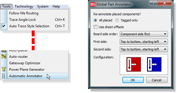
The Automatic Annotator command on the Tools menu and the Global Part Annotator dialogue it opens
The effects of running the command are identical to manual annotation, namely that it will simply happen with live netlisting enabled and that it will switch the layout into a locked state with live netlisting disabled.
The Use sheet offsets option on the dialogue refers to the initial annotation offset available for sheets on the schematic. Some users prefer that each logical block (sheet) on the schematic has its own annotation base, which is set on the schematic by the Annotator Init field of the Edit Sheet Properties dialogue. Where those offsets are set up, ticking Use sheet offsets makes the annotation pass on the layout honour them.
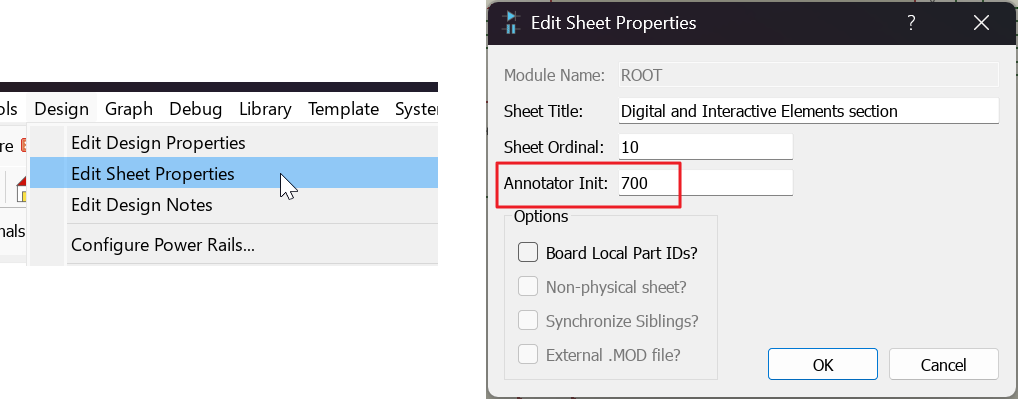
The Annotator Init field on the schematic Edit Sheet Properties dialogue, which sets a sheet's annotation base
Obviously, the position of parts on a layout is completely arbitrary and any attempt to sensibly re-annotate the board relies on heuristics. While generally a global re-annotate will perform sensibly it does very much depend on the individual board topology and you may need to make some manual adjustments.