RATSNEST FEATURES
Overview
The term Ratsnest is used to describe the pattern you get on the screen when the pin to pin connections specified in the netlist are shown as single straight lines rather than copper tracking. Once a netlist has been loaded and the components placed (or vice versa for that matter) the ratsnest gives a good visual impression of the complexity of the routing task that is before you or the autorouter. Furthermore, it gives an indication of the quality of component placement since the presence of lots of long ratsnest lines suggests that some components would be better placed closer together.
Automatic Ratsnest Re-calculation
Proteus keeps the ratsnest up to date and optimised at all times. Add a component or delete a track and new ratsnest lines will appear. Make connections and ratsnest lines will disappear. It's as simple as that.
The term 'optimisation' refers to that fact that Proteus always displays the 'Minimum Spanning Tree' for each net. This means that the displayed ratsnest lines always represent the shortest interconnection pattern between the pads.
From the Design Rule Manager (Net Classes tab) you can specify a different colour for ratsnest lines of a particular net class. For example, you may have green ratsnest lines for SIGNAL traces and blue ratsnest lines for POWER traces. This is particularly useful as these colours are maintained during part placement, allowing you to make sensible decisions about the best position and rotation for the footprint.
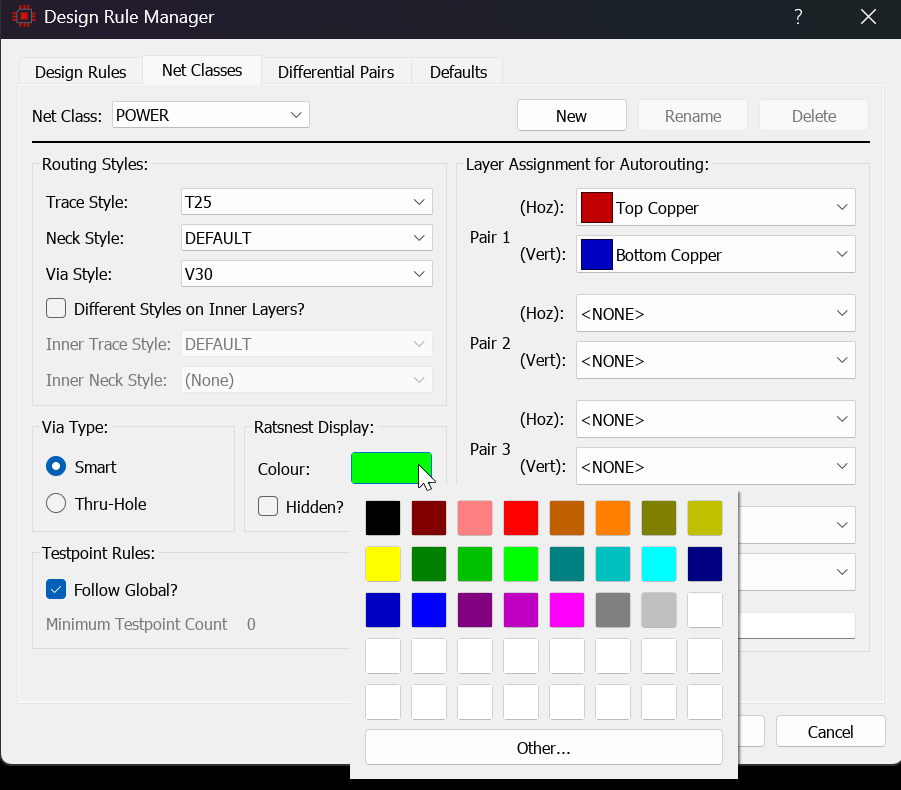
The Net Classes tab of the Design Rule Manager, where the ratsnest colour for a net class is set
The ratsnest can also be turned off wholesale with the Ratsnest checkbox on the Edit Layer Colours/Visibility dialogue form, which you reach from the View menu (CTRL+L). Ratsnest lines belonging to a particular net class can be turned on and off independently in the Design Rule Manager on the Technology menu: the Net Classes tab carries a Ratsnest Display group with a Colour: swatch and a Hidden? checkbox for the selected class.
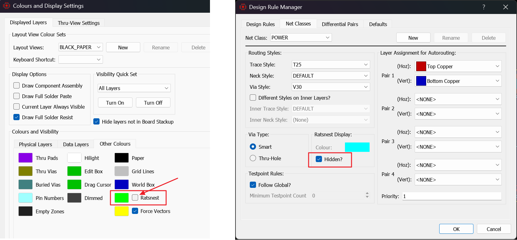
The Ratsnest checkbox on the layer colours and visibility form alongside the per net class Ratsnest Display group in the Design Rule Manager
Dynamic Ratsnest
The ratsnest is intelligent and designed to help you quickly and easily manually place routes. When you initiate manual route placement on a netlisted design the ratsnest will change to indicate the nearest termination point (said point being highlighted for additional emphasis) to the current location of the mouse. Further, a 'shadow' trace will appear over the area that has already been tracked to indicate the layer and position of the area already tracked. The termination point and ratsnest indicator will update in real time as you move providing you with constant feedback on route termination.
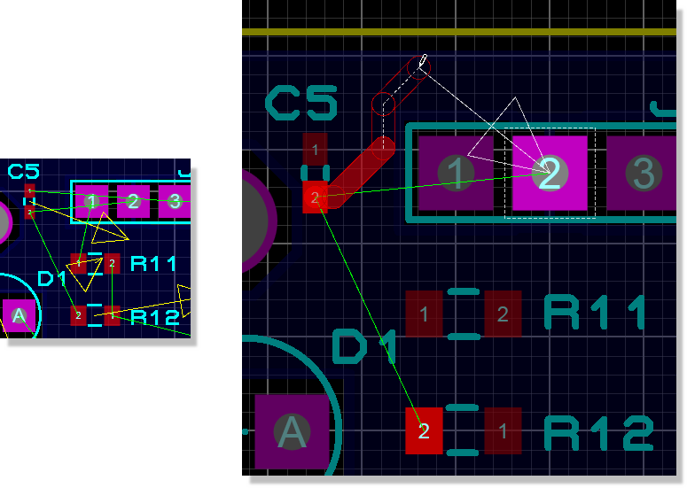
The dynamic ratsnest indicating the nearest termination point while a route is being placed manually
Force Vectors
Force vectors are provided as a further aid to component placement. They appear as arrows, yellow by default, which point from the centre of each component to the point where its ratsnest length (as defined by its current ratsnest lines) would be shortest. Another way of thinking about them is to consider each ratsnest line as a rubber band. The force vector then points to the place where the component would move to if released (strictly speaking this would also depend on the elastic linearity of the rubber bands, but we won't get into that; it's a good analogy!)
One oddity that can arise is that if you move the component to the position marked by the tip of its force vector, the ratsnest itself may change because a better minimum spanning tree may then be found. This can mean that the force vector then points to somewhere slightly different. We do not regard this as solvable; most PCB packages do not re-optimise the ratsnest after each edit, so such effects would not be so obvious, but they are still there.
The force vectors can be turned off with the Force Vectors checkbox on the Edit Layer Colours/Visibility dialogue form, which you reach from the View menu (CTRL+L); this setting is persistent across layouts. Their colour is configured on the same form, so yellow is only the default.
Ratsnest Mode
Ratsnest mode is selected by clicking left on the Ratsnest icon. You can then
- Specify connections manually, if you are working without a schematic but still wish to use the auto-router.
- Perform pin and gate-swaps (where legal) by dragging ratsnest lines from one pad to another.
- Tag all the connections for one net by selecting the net in the Object Selector and clicking left on the 'T' toggle.
Clicking right on a ratsnest line opens its context menu, which carries two commands:
- Manual Pinswap/Gateswap, which begins the drag operation described under Manual Pin-Swap/Gate-Swap.
- Delete, which removes the connection you are pointing at.
Either command may be greyed out for the connection you have picked. Delete in particular applies only to connections you entered by hand: a connection that came through from the schematic belongs to the netlist and cannot be deleted on the layout.
In conjunction with the autorouter's ability to route all, tagged or untagged connections, ratsnest mode gives you the means to autoroute the board selectively.
Proteus supports manual ratsnest entry in much the same way as you would manually route a track (with the ratsnest icon selected). You can then use the autorouter normally. Note however, that this is a less than ideal way to use the software and where possible boards should always be netlisted from the Schematic Capture module or another suitable schematic package.
Manual Ratsnest Entry
If you are working without a schematic, it is possible to enter ratsnest connections manually. Connections are specified by clicking left the pads to be interconnected. Proteus will automatically create net-names for connections specified in this way.
Note that where component pads are on single layers, you must use the layer selector to select the correct layer for each pad. If a ratsnest line must change layer, then you can press the SPACE bar to toggle between top and bottom whilst placing the ratsnest line.
Connections entered by hand are also the only ones you can remove on the layout. Point at the connection, click right and choose Delete from the context menu. A connection that arrived from a schematic netlist cannot be deleted here; edit the wiring on the schematic instead and let the netlist remove it.
This is not a recommended mode of working as many features, particularly power planes and design rule management, require netlist information and such functionality will not be available without a schematic netlist.
See Also: