CADCAM OUTPUT COMMAND
Overview
All CADCAM output, that is the Gerber files, the NC Drill files and the Tool Information readme, is generated from a single command: Output Menu > Generate Gerber/Excellon Files. The window it opens is titled CADCAM (Gerber and Excellon) Output and has two tabs, CADCAM Output and CADCAM Notes.
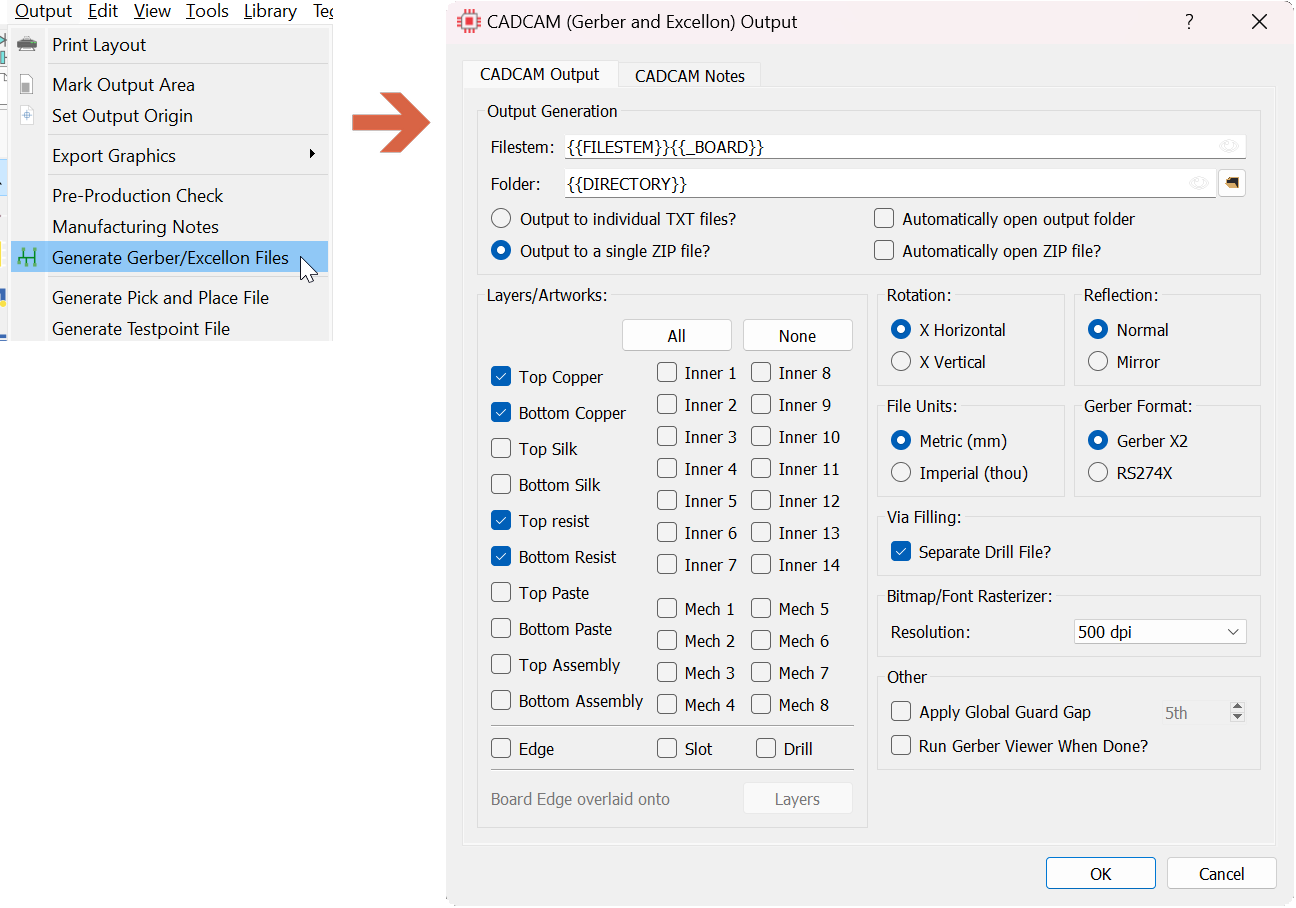
Launch the CADCAM form from the Output menu
Output Options
The dialogue form allows you to select:
- A common filestem and location for all files produced. This defaults to the layout filestem but a neat trick is to change it to something like C:\GERBER\MYBOARD such that all files produced will go directly into a location of your choice. Both fields accept field codes. The eye button at the right hand side of each field toggles the display between the field code expression and the resolved text; it does not fill anything in.
- Whether you want all the output files to be collated in a single ZIP archive or left as a collection of individual TXT files in the folder of your choice. Depending on your choice you can then opt to automatically open the output folder or the ZIP archive on completion, allowing you to browse the CADCAM files.
- Which layers you wish to output for the current design. This will be defaulted automatically based on an analysis of what is contained in the layout.
- Whether the screen X co-ordinate is directed to the CADCAM x co-ordinate (X Horizontal) or to the CADCAM y co-ordinate (X Vertical).
- Reflection, either Normal or Mirror. Mirror flips the artwork, which some board houses ask for on bottom-side films.
- File Units, either Metric (mm) or Imperial (thou). This sets the units used inside the Gerber and drill files themselves, so check which your manufacturer expects.
- Whether the newer Gerber X2 or the older RS274X Gerber format is used. Gerber X2 contains several major advantages and is the recommended output format.
- The option (recommended) to export filled vias (NCVF) in a separate file. This split applies to plated through-hole vias only; blind, buried and laser-drilled (micro-via) spans are always exported with all vias in a single pass regardless of filling status.
- What resolution is used for rastering truetype fonts and bitmaps. A finer resolution will result in smoother edges but can result in the generation of very large files.
- Apply Global Guard Gap, which overrides the per-pad solder resist expansion with a single clearance across the whole layout, together with the value to use.
- Include All SMT Pads in Paste Layers?, which forces every surface mount pad into the paste artwork rather than only those pads the design rules would normally paste.
- Whether or not to launch the Gerber Viewer module automatically on production of the CADCAM files. This option will load the CADCAM files into the Gerber Viewer on completion, allowing you to view the resulting output prior to sending the files to your PCB manufacturer for prototyping.
You can set a default directory for CADCAM output via System Menu > System Settings, in the PCB Design Settings section.
Board Edge Layers
Beneath the layer selector, the Board Edge overlaid onto Layers button opens the Edge Layers dialogue. This lists the artworks onto which the board edge graphic is overlaid, with All and None buttons to set them in one go. Overlaying the edge onto a copper or silkscreen artwork gives the board house a visible outline on that film.
The board edge is always output to the profile file whatever you select here, so you cannot lose the outline by clearing this list.
CADCAM Notes
The CADCAM Notes tab holds the text that is placed into the readme file generated with the CADCAM output. The readme also lists all files generated together with the tool settings for the photoplotter and the drilling machine.
Project Notes
Two checkboxes, Manufacturing Notes and PCB Specification Notes, include the corresponding documents from the Project Notes module in the output fileset as a PDF.
Basic Notes
A legacy field whose contents are placed directly in the CADCAM readme file. It is retained so that older designs keep their notes; for new work use the Project Notes documents above.
Contact Details
Contact details for whoever the board house should call about the design. These are placed automatically in the CADCAM readme file.
Notes on Generation
Any files generated from a previous run but now corresponding to a disabled layer are deleted, because the new tool information table may be wrong for them.
Context sensitive help is available for all options on the dialogue form, providing detailed information on the functionality of each field.
If you opt to view the resulting CADCAM you will open the Gerber module in View mode. To edit or panelise you must first close the current project and then open the Gerber module. See the section on panelisation for more information.
See Also: