GERBER OUTPUT
Overview
The Gerber format, named after Gerber Scientific Instruments Inc., and now owned by Ucamco, remains one of the most widely used in the PCB industry as regards specifying PCB artwork.
A photoplotter is essentially the same as a pen plotter except that it writes with a light beam on photographic film rather than with an ink pen on paper. The aperture through which the beam shines can be varied, allowing it to expose a pad in a single flash and a track with just one movement of the plotting head.
In order for a photoplot to be produced (usually by a bureau, as photoplotters are not cheap) it is first necessary to set the machine up with a set of apertures corresponding to the various pad shapes and track widths used on the board. Each different aperture is referenced by a so called D Code in the Gerber file and a table listing D Codes against aperture shape and size must thus be compiled. This table is compiled automatically and then written out as part of the tool information file.
Proteus will automatically dedupe if two pad styles result in the same aperture, and it will only use one D code in this situation. Also, styles which are present in the selectors but not used on the board do not waste table space.
A note on Gerber Versions:
- The original RS274D Gerber format was deprecated many years ago and is no longer supported in Proteus as it cannot handle the demands of modern PCB design.
- Extended Gerber, commonly known as RS274X is still widely used and remains supported in Proteus. However, there is only one drill file (layer ranges specified in readme file) generated and there is no netlist.
- Gerber X2 is the latest output format from Ucamco and is the default option in Proteus. Amongst other benefits, it contains both a bare copper netlist (IPC-D-356A), separate drill files per drill range and plated status. It is also fully backward compatible with RS274X Gerber viewers and integrates with the Proteus manufacturing report.
Gerber RS274X Format
RS274X includes many high level commands and controls that let the creator of the Gerber data specify the photoplot very precisely and therefore represents a full image of the PCB. However, there are several points to bear in mind:
- Truetype text and bitmaps will be rasterised in the resulting output files to ensure accuracy.
- The origin for the Gerber co-ordinate system is defined by the Set Output Origin command on the Output menu.
- Drilling information is exported as a single Excellon drill file with layer ranges identified in a human readable readme.txt file.
RS274X is now an old format and not really suitable where your board implements technologies that are more recent than the standard. In particular, if you work with blind vias, buried vias, via filling or panelisation you should use the Gerber X2 format. Generally speaking, unless you have a good reason not to you should use the Gerber X2 format because it provides more information to your board manufacturer.
Gerber X2 Format
Gerber X2 is the recommended output format in Proteus.
The  Gerber X2 format basically adds the ability to attach attributes to the Gerber files. The attributes provide additional information about the image which is also known as meta-information. Examples of some of the attributes include:
- File Function: is the file the top soldermask or the bottom copper layer?
- Part: does the file represent a single PCB, an array, a coupon?
- Pad Function: is the flash an SMD pad, a via pad, a fiducial?
These attributes do not impact what the image looks like, however, they do provide the PCB manufacturer with useful information to aid in building the PCB to the correct specifications. Ucamco calls it adding intelligence to the image. Additional information such as which pads are via pads allows the CAM operator to properly set up the soldermask for the board. By contrast, in Gerber version 1 this type of information had to be provided in drawings or notes which are manually read and interpreted by the CAM operator. Any oversight or misinterpretation by the operator would ultimately cause errors and delays.
Advantages to Gerber X2 export include:
- Bare copper netlist included (IPC-D-356A format).
- Top and Bottom Assembly Layer data can be included.
- Improved handling of drilling information.
- Attribute information included as metadata, providing additional information to manufacturers. For example, a fiducial is explicitly defined as a fiducial.
- Panelisation in Proteus requires the Gerber X2 output format as it contains a superior dataset.
Drilling Information Files
Almost all numerically controlled drilling machines in PCB manufacture use the Excellon format, invented by Excellon Industries. The format is very simple, consisting of the (x,y) locations of the holes and T Codes specifying which tools to use. As with Gerber Format, a table is created within the Tool Information File that lists the hole diameter corresponding with each T Code. Proteus handles this in the same way as it handles each Gerber D Code: it assigns a new T Code for each new hole size it encounters, and this information is also put in the tool information file.
The handling of drill file data is however significantly different in Proteus between the older RS274X format and the newer Gerber X2 format.
Drill Files
With RS274X there is only one drill file produced (Excellon drill file) and the drilling range is detailed in the accompanying readme.txt file.
With Gerber X2 you get a separate drill file for each drill range in the layout. These files are standard X2 Gerber Files, not Excellon drill files. You also get separate drill files for plated and unplated holes. On HDI boards, drill files for laser-drilled micro-via spans include a (Laser/Micro-via) annotation in the tool table to distinguish them from CNC-drilled spans.
Slots
With RS274X, in-pad slots are exported in the drill file. Holes in the board from either the edge layer or the slot layer are output in the profile file alongside the board edge itself.
With Gerber X2, in-pad slots (from padstacks) are output in the appropriate plated or unplated drill file with an AperFunc of ComponentDrill or MechanicalDrill. Holes in the board from either the edge layer or the slot layer are output in the profile file alongside the board edge itself.
In both formats, where a padstack hole or slot has an offset from the pad origin, the drill data is output at the correct offset position. No additional configuration is needed.
See Also:
Handling of drill holes in RS274X has been left unchanged as a legacy format and is expected to be deprecated entirely in due course. We recommend use of the Gerber X2 format.
In both formats, the drill sizes used are taken from the Drill Hole attributes of the pad styles. Please make sure that the default sizes we have allocated are suitable for your application before having large numbers of boards manufactured.
README Text File
The readme file is exported with all CADCAM formats and provides summary information split into several categories.
The following screenshots are for Gerber X2 format. The exact contents will be output dependant as some features are supported only in certain formats.
File Listing
A checklist of the fileset that should accompany the readme file.
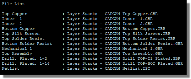
The file listing section of the CADCAM readme, checklisting every file in the fileset.
Photoplotter Setup
A summary of D Codes and parameters for photoplotter setup.
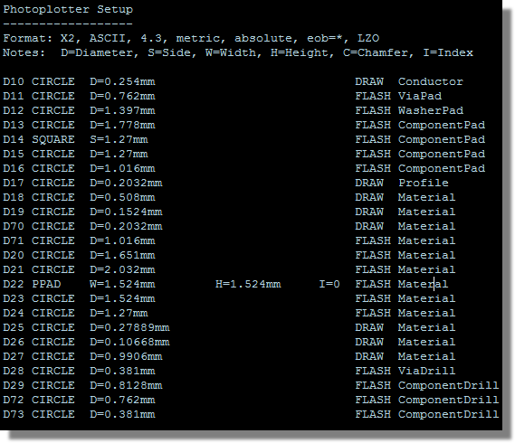
The photoplotter setup section of the readme, listing each D Code against its aperture shape and size.
It is worth pointing out that if you have any Testpoints on your board then these will appear in the right hand column as TestPad as opposed to ComponentPad.
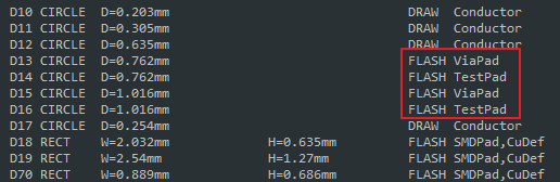
Testpoint pads reported as TestPad rather than ComponentPad in the readme aperture table.
If a footprint or package pad is also marked as a Testpad, the rules state that it will be marked as a ComponentPad first and foremost. If it is a singular pad (not part of a footprint) and marked as a testpoint pad in the layout, it will be listed as a Testpad.
Drill Tool Table
A listing of every T Code against its hole diameter and the drill range it applies to. On an HDI board, the entries for a laser-drilled span carry a (Laser/Micro-via) annotation so that the drill house can see at a glance which spans go to the laser rather than the CNC drill. The tool type is reported as Microvia, or as Filled Microvia where the via style is marked as filled, so the readme also records the fill requirement for each micro-via span.
Layer Stackup
A tabular listing of the specified layer stackup for the board.
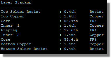
The layer stackup section of the readme, listing each layer and its material and thickness.
IPC-D-356A Netlist Format
The IPC-D-356 format was designed to define a standard netlist format by which bare board test information can be represented. In the simplest of forms, this means it must be able to store netlist information along with XY coordinates, and even reference designators and pin numbers (if they exist). It is used by PCB manufacturers to bare board test the PCB before assembly and population with components.
In Proteus, the export of the IPC-D-356 netlist is automatically included with the Gerber X2 export fileset. Supplying it satisfies the CAD data requirement of IPC-9252 (section 5.1.2), the standard governing electrical test of unpopulated boards, and the netlist gives the fabricator an independent check on the image data.
It can also be produced on its own, without generating a whole CADCAM fileset, using the Generate IPC-D-356 Netlist command on the Output Menu. Proteus prompts for a filename and writes the netlist immediately. This is the quickest route when a board house comes back asking only for the netlist.
File Extensions
The file extensions used with Gerber export are:
- .GBR : Gerber image file.
- .DRL : Drill file (RS274X only).
- .IPC : Netlist file (Gerber X2 only).