MANUFACTURING REPORT
Introduction
As PCB design becomes more complex and boards more intricate, the need to supply additional information to the board house has increased. Proteus has two template reports that can help, namely:
- PCB Manufacturing Report
- PCB Specification Report.
Both can be accessed via the Project Notes module. Either open the Project Notes module and select the report you want from the template list or, if you already have a note open, select the New Note command from the File Menu to add another one. The module needs to be unlocked to enable the new note command.
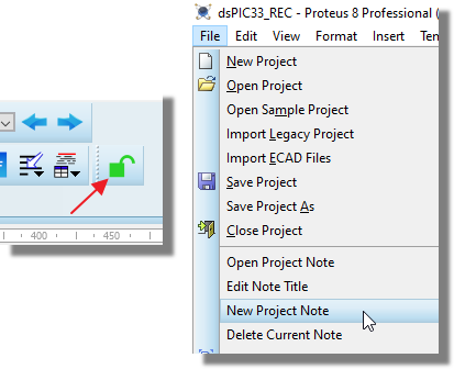
Creating a new note from the report template list in the Project Notes module.
The PCB specification report is a template for fabrication requirements ranging from materials used to silkscreen colour to testing, quality and packaging requirements. Typically, this would be updated or changed to reflect your corporate guidelines. Meanwhile, the PCB manufacturing document discussed below contains important information about your PCB that is not clear or explicit in the standard Gerber files.
You can include either or both of these reports automatically with the Gerber fileset by selecting Manufacturing Notes and/or PCB Specification Notes from the CADCAM Notes tab on the CADCAM Output dialogue form.
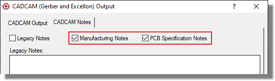
Selecting the Manufacturing Notes and PCB Specification Notes checkboxes on the CADCAM Notes tab.
Content
The manufacturing report consists of several sections which in turn include data objects with information from the PCB. It is important to understand that these data objects can be inserted or removed as you please and it is perfectly possible therefore for you to create your own custom manufacturing report. With imagery such as artwork in particular you may wish to have multiple objects showing different views of the board.
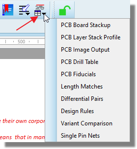
The list of project data objects available for insertion into a note.
Board Stackup
PCB Board Stackup is a table that contains material information and thicknesses for various layers and cores on the board. This information is configurable in Proteus via the Set Layer Stackup command in the PCB module. The table will generate using the current units, imperial or metric. You can regenerate the table after changes via the right click context menu command.
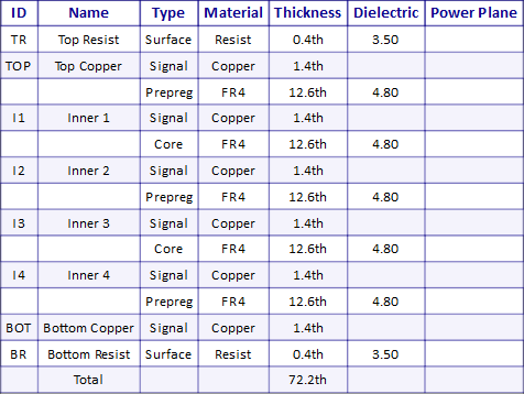
The board stackup table showing layer materials and thicknesses.
Layer Stackup
PCB Layer Stack Profile is a visual showing the drill ranges used in the PCB and is essentially the same graphic as you would see at the end of the layer stackup configuration process. It is most helpful for multi-layer boards where the choice of construction methods (internal cores versus external cores) impacts on drill ranges. It can be removed for 2-layer PCBs or where no blind or buried vias are used.
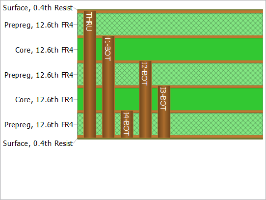
The layer stack profile graphic showing the drill ranges used on the board.
See Also:
Drill Table
PCB Drill Table is a listing of all hole sizes and styles used on the board along with their layer ranges. Of particular interest is the count field, which can help identify loose vias for example which may be changeable to a more prevalent via style to save manufacturing costs.
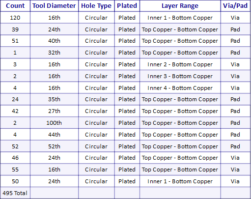
The drill table listing hole sizes, styles, layer ranges and counts.
Microvia Compliance
On HDI boards, a Microvia Compliance data object can be inserted into the report. This generates a detailed audit of every micro-via on the board.
The table has nine columns: Location, Net, Style, Layer Span, Hole Dia, Aspect Ratio, Drill Span, Filled and Compliant.
Three of those columns carry the audit itself:
- Drill Span records whether the micro-via's layer span is a valid drill span in the board stackup.
- Filled records whether the via is marked as filled.
- Aspect Ratio is the ratio of drilled depth to hole diameter. A ratio above 0.75:1 is reported as a warning, since IPC-2226 recommends that laser-drilled micro-vias stay at or below 0.75:1. A ratio above 2:1 is reported as a failure. Where the board has no valid stackup, or the drill depth cannot be determined, the cell reads N/A.
The Compliant column is a worst-of roll-up of those three results. It shows a failure if the drill span is invalid, or the via is not marked as filled, or the aspect ratio exceeds 2:1. It shows a warning if the only issue is an aspect ratio above 0.75:1. Otherwise it shows a pass. Reading down the Compliant column is therefore enough to find every micro-via that needs attention before you generate CADCAM output.
If the design contains no micro-vias at all, the table reports a single row reading "No microvias found in design".
The Pre-Production Checklist tests the same three things and several more besides, including the annular ring on every via, the IPC-2226 maximum hole size for a micro-via, and whether a DRC room with micro-via mode enabled actually uses a micro-via style. Those additional checks are not part of this data object, so a board can be clean here and still raise a micro-via warning in the checklist. Use this table for the per-via breakdown that goes into the manufacturing pack, and the checklist as the gate before output.
Pre-Production Check Results
A Pre-Production Check data object places the results of the pre-production checker into the report as a formal table, so that the evidence that the board was checked travels with the manufacturing pack.
The table has two columns, Result and Message, and two sections. The results section lists every log line the checker produced, each tagged with its outcome: a tick for a pass, a cross for a failure, a warning symbol for a warning, or TEST, SKIPPED, ERROR, Date and File for the structural lines. The summary section that follows counts the Errors, Warnings, Failed, Skipped and Passed entries.
The table reports the results of the last check that was run. If no current results are available, the object reports that fact and tells you to run the Pre-Production Check from the Output menu; run the checker first, then regenerate the data object.
Board Information
A Board Information data object summarises the board itself in a two-column Property and Value table. It reports the filename, the board dimensions in both inches and millimetres, and counts of objects, pins, vias, holes, traces, nets and missing connections, together with the total routed and unrouted lengths. Where drill symbols have been assigned, a further section lists each hole diameter and the number of holes of that size.
Assembly Drawings
These are artwork drawings for both top and bottom assembly. You can configure layer display for these via the right click context menu, or remove them altogether if for example placement is only on one side of the board.
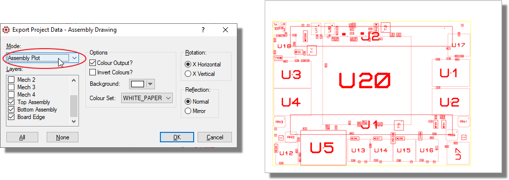
Top and bottom assembly drawings placed in a project note.
See Also:
Fiducial Positions
The PCB Fiducials table contains the co-ordinate locations of all fiducials on the PCB. This information may be useful for your board house if they are commissioned to handle component placement or use automatic insertion machines.
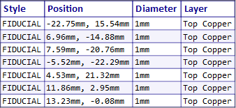
The fiducials table listing the co-ordinates of each fiducial on the board.
Note that Proteus identifies fiducials as pad styles beginning with the word FIDUCIAL (for example FIDUCIAL20). If you have not created fiducial styles, or have imported library parts that do not make use of the fiducial styles, then they will not appear in this table.
PCB Artwork
The PCB Artwork section of the report by default contains a single view of the board containing all the layers. You can edit the displayed layers as required for your project from the right click context menu command (re-configure project data). For example, a top view might contain only top silk, top copper and top resist.
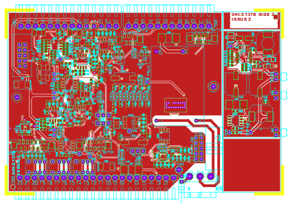
A rendered PCB artwork image placed in a project note.
You can add additional board views by inserting a new PCB Image Output data object.
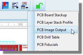
Inserting a further PCB artwork data object to add another board view.
On large multi-layer PCBs a full render of all the layers can result in a very big file size and is unlikely to provide much detail for analysis. Better to have multiple, different views of the board each containing less information.
Other Data Objects
The sections above describe the objects that appear in the supplied manufacturing report template. The full set that the PCB module can supply is larger, and any of them can be inserted into a report of your own:
- PCB Board Stackup
- PCB Layer Stack Profile
- PCB Image Output
- PCB Drill Table
- PCB Fiducials
- Length Matches
- Differential Pairs
- Design Rules
- Testpoints
- Net Testpoint Count
- Pre-Production Check
- Microvia Compliance
- Board Information
Design Rules reproduces the design rule report, while Testpoints and Net Testpoint Count give the testpoint co-ordinates and the per-net testpoint coverage. Between them they cover much of the same ground as the standalone Testpoint Information File, in a form you can put straight into documentation.
Customising the Report
It is perfectly possible to customise the report both in terms of content and style. You can only edit when the note is unlocked; click on the padlock on the top menu.
Data objects can be added via the Insert Menu > Project Data or directly from the data object icon on the toolbar.
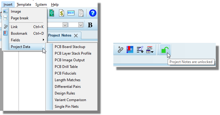
Inserting a project data object from the Insert menu.
Data objects can be deleted by right clicking on them and then selecting the delete option from the resulting context menu.
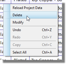
Deleting a project data object from its right click context menu.
From a styling perspective all the colours and fonts are CSS styles. You can edit styles to configure as needed.
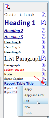
The style editor listing the CSS styles used by the report.
Paper size and orientation is configured via the File menu.
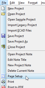
Setting the paper size and orientation from the File menu.
Once you have set up you need to identify the note as a manufacturing note so that it can be included with the Gerber files. To do this, edit the note title from the File Menu, change the name and make sure the note type is manufacturing report.
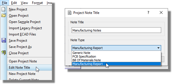
Setting the note type to manufacturing report in the note title dialogue.
You can only have one manufacturing report and one PCB specification report per project. Other reports will typically be of type generic.
Now, save as template from the template menu to make your report available in future designs.
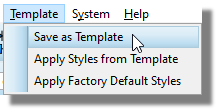
Saving the report as a template for use in future designs.