DESIGN RULE EXAMPLES
Introduction
This section of the documentation provides some examples to re-inforce the contents of the previous topics. In the following discussion assume that we have drawn the schematic, netlisted the design, and now need to create some design rules to determine the design rule constraints of a 4 layer board.
Every board starts with a default rule which can be edited, however if you require more specific rules, follow the below information.
Setting up a Rule that Applies to a Layer
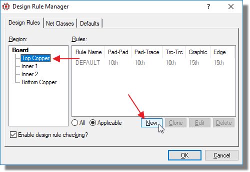
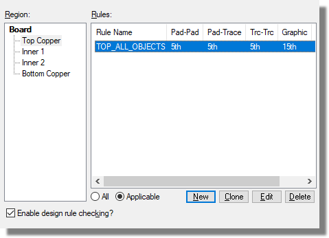
Lets say we would like to have a Rule that stops any object (Track, Pad or Via) on Top Copper from being closer than 5th away from any other object. In the Design Rule Manager, Select the Top Copper Layer and click 'New':
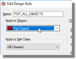
Next we need to give the rule a sensible name and assign the rule to the required area of the board. In this case it applies to TOP Copper.
As we want the rule to apply to all objects, we can leave Net classes set to 'All Classes' and 'With Respect to' also set to 'All Net Classes'.
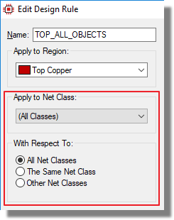
This means that All objects on all Net Classes on TOP Copper will adhere to the rule. Next you set the distance that is the minimum distance allowed for all objects to get close to
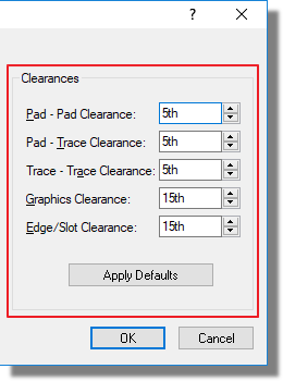
Click OK to set the Rule. And you will see the following:
Setting up a Rule that Applies to a Net Class
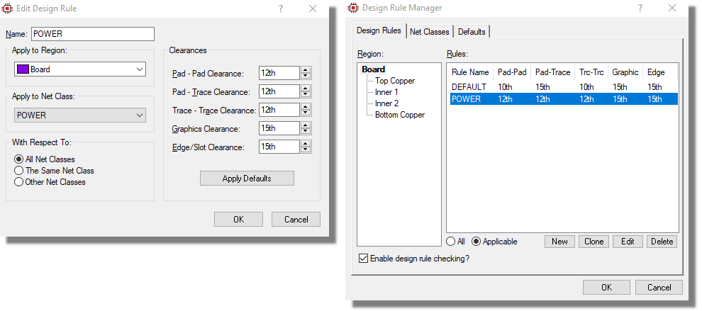
In this example, we require a 12th rule that applies to the POWER net class which will apply to all layers and any net class including itself.
1. Open the Design Rule Manager from the Technology menu.
2. Click on the New button
3. Give the Rule a name. For this example we can call it POWER.
4. Make it apply to the BOARD
5. Apply to Net Class -> Drop the list down and select POWER
6. With Respect to ALL Net Classes and you should see something like the following:
Setting up a Rule that Applies to a Design Room
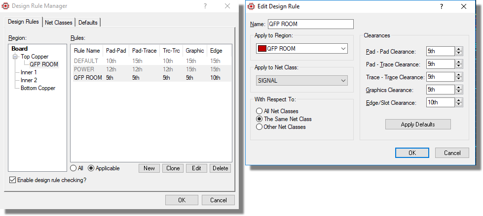
You can set constraints on a specific area of the board. These areas are called Design Rooms; see here for more information. Assuming that you have placed a Room, open the Design Rule Manager and create the rule that you need inside the room. Lets say that the rule we want is a 5 thou clearance for the SIGNAL net class with respect to itself, applying inside the room.
- Click on New.
- Create the Rule name.
- Set Apply to Region to be the Design Room, which will appear under the name that you gave the room.
- Set Apply to Net Class to be SIGNAL.
- Set With Respect To to be Same Net Class.
- Set the clearances, and you should have the following:
Analysis
With the above there are four rules in place and a hierarchy of Rules.
- The Class-Room rule created above takes precedence over all the other rules in this example.
- The Net class rule over rules the Layer rule.
- The Layer rule is above the Default rule.
- The Default rule will cover anything that is not covered in the above rules.
Note the naming. The third rule is scoped to a net class inside a room, which makes it a Class-Room rule rather than a plain Room rule. The distinction matters because the two sit at different levels: the full ladder has nine levels, and a Class-Room rule outranks a Room rule.
The rules hierarchy is explained further here.
Setting up an Exclude Foreign Room
In this example we have a transformer on the board whose datasheet specifies that no foreign copper may be present beneath the component on the top and inner copper layers. We want the DRC checker to enforce this automatically.
To set up the exclusion zone:
- Select the room icon and drag out a room that covers the component footprint and the required clearance margin around it.
- In the Edit Room dialogue, switch to the DRC Room tab. Give the room a name (e.g. XFMR_VOID), set the layer range to cover Top Copper through to the required inner layer, and check the Exclude Foreign checkbox.
- Click OK to close the dialogue.
- Now group the room with the transformer component: tag both the room and the component (using a tag box or CTRL+click), right click and select Group Objects from the context menu.
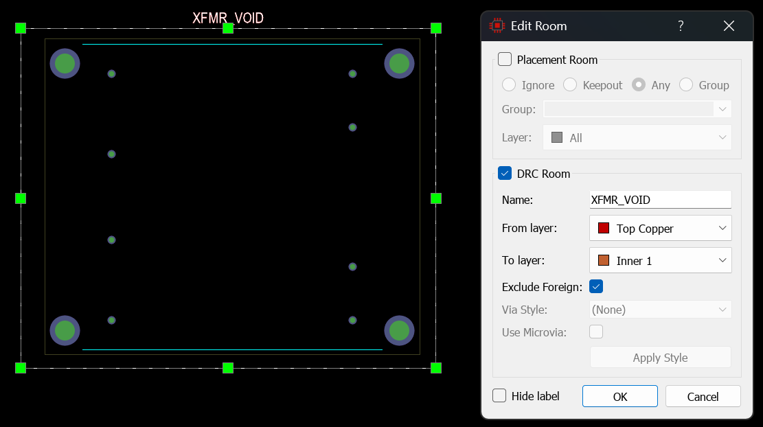
A DRC room with Exclude Foreign enabled, grouped with a transformer component. The room boundary defines the exclusion zone on the specified copper layers.
The DRC checker will now flag any copper inside the room boundary that does not belong to the transformer or its connected traces. Zone fills will automatically punch a void matching the room shape on the specified layers.
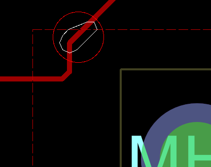
DRC violations flagged on foreign copper inside the exclude foreign room. The transformer's own pads and connected traces are exempt.
Because the room and component are grouped, moving or rotating the transformer will also move the room, keeping the exclusion zone correctly aligned. This is the intended workflow: define the spatial relationship once, then group so that it is maintained throughout the design process.
Grouping also changes what happens when you delete. Right clicking the transformer and deleting it from the context menu deletes the whole group, so the exclusion room goes with it. The same is true in reverse: deleting the room deletes the transformer. This applies to a single object deleted from the context menu; a multiple object selection deleted as a block removes only what you tagged. If you want to remove one member and keep the rest, use Ungroup Objects first, remembering that ungrouping dissolves the entire group tree from its root rather than just the innermost sub-group.
The same technique can be applied to other scenarios where a component datasheet defines clearance or keep-out requirements: BGA components with escape area constraints, connectors with clearance envelopes, or high-voltage components requiring safety isolation distances.
Previously, creating a copper void beneath a component required placing an empty zone on each copper layer individually. An exclude foreign DRC room replaces this with a single object that covers all of the room's layers, is DRC-enforced, and moves with the component when grouped.
See Also:
Grouping a Zone with a Component
Object groups are not limited to DRC rooms. Any object in the object database can be grouped, including zones. A common application is to group a local copper pour with the component it serves so that the two remain aligned when the layout is adjusted.
In this example we have an ADC whose datasheet specifies a solid ground plane directly beneath the IC on an inner layer for return current integrity. We want to ensure that the ground island stays aligned with the ADC if it is repositioned.
To group a zone with a component:
- Place the ADC component on the board and route its connections.
- Select the zone icon and draw a zone on the required inner layer, covering the area beneath the ADC. Assign the zone to the appropriate ground net.
- Tag both the zone and the ADC component (using a tag box or CTRL+click), right click and select Group Objects from the context menu.
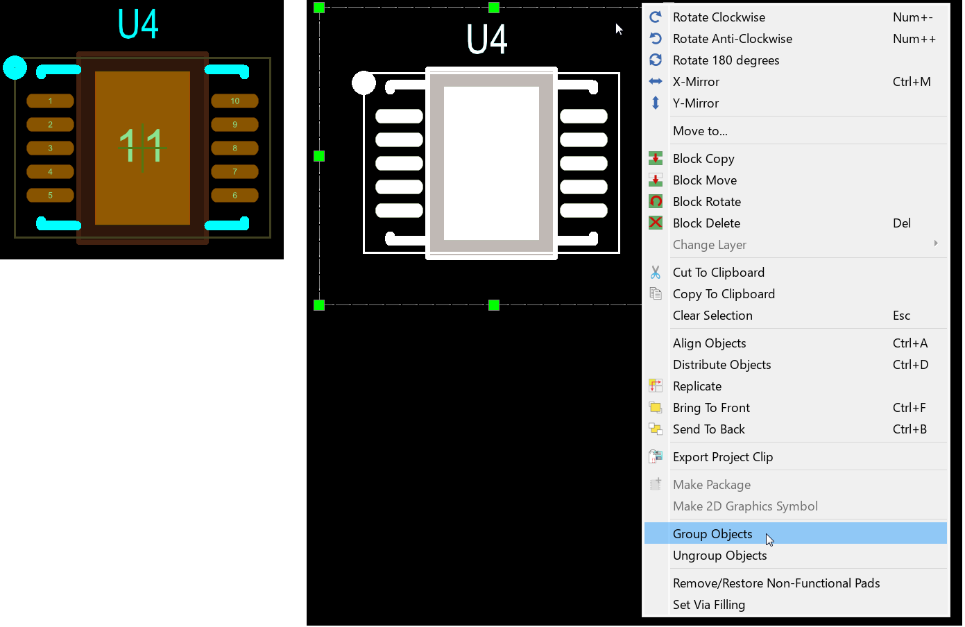
A local ground zone on an inner layer grouped with the ADC component above it. Moving the ADC will move the zone and the zone fill will regenerate automatically.
When you drag or move the ADC, the grouped zone moves with it. The zone fill regenerates automatically after the move, reflecting the new position of the zone boundary and the obstacles around it.
This technique is also useful for thermal pads. An exposed-pad QFN component with a copper zone for heat spreading on inner layers can be grouped so that the thermal design stays intact when the component is repositioned.
As with the exclusion room example above, grouping ties the two objects together for deletion as well as for movement. Right clicking the ADC and deleting it from the context menu deletes the grouped ground zone too, and deleting the zone deletes the ADC. This applies to a single object deleted from the context menu; a multiple object selection deleted as a block removes only what you tagged. Use Ungroup Objects first if you want to keep one of them, remembering that ungrouping dissolves the entire group tree from its root.
See Also: