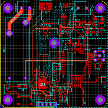
ROUTING
Routing the Board
Having configured the board constraints we can now move on to actually making connections and routing the board.
You can load the "IoT Pump - Unrouted" sample design in order to continue from this point, if you have not already successfully completed the previous sections.
Manual Routing
Before we start, we will want the ratsnest lines turned back on. If you have them disabled (can't see any green lines between pads), turn them on from the View Menu - Displayed Layers dialogue.
When routing a board which features "high-speed" / impedance-controlled traces then it is generally a good idea to route the high-speed traces first, so that the other traces can be routed around these more sensitive tracks (rather than trying to route the more sensitive impedance-controlled traces later around and through a potential network of existing "lower-priority" tracks). In our design we will be treating the USB, SPI and ICSP lines as high-speed traces. Whilst the SPI and ICSP are not "really" high-speed connections, we will be treating them as such in this design in order to demonstrate the relevant features without resorting to an overly complex tutorial design. In addition, our antenna traces (GSM / BlueTooth) are also impedance-controlled traces, and we will route these manually as well. In general, manual routing (as opposed to auto-routing) is used where we need more specific control over track position / path.
Before starting with manual routing let's look at how routing works and various configuration options. There are two main ways to route in Proteus, namely Push mode and FMR mode. You can toggle the routing mode at any time with the SHIFT+P keyboard shortcut.
Push Mode
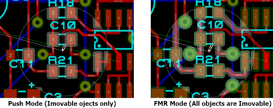
This is the default mode and allows you to move tracks and vias out of the way of the route being placed while obeying all design rules. Generally faster and more productive routing as it doesn't involve a lot of manual editing to make space for route placement. Also superior in densely packed regions of the board.
FMR Mode
This is also a fully design rule aware routing mode but will treat all objects as immovable. Useful for hugging tracks and where you want total control over all route topology. FMR mode is also needed if you want to place routes with curved corners as this is not currently supported in Push Mode.
Mode Switching and the Status Bar
You can switch between modes using the SHIFT+P keyboard shortcut. This will work at any time including during route placement, meaning for example that you can start placing a route in push mode and then switch to FMR mode to hug another route. The current routing mode is shown along with other route information on the status bar during route placement.
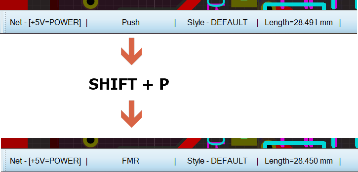
Switching modes displays on the status bar during route placement
Route Command Centre
You can fully configure routing from the route command centre (keyboard shortcut R). This will also work at any time, including in the middle of route placement. This provides another way to change routing modes (although less fast) but also gives you control over what objects are pushed and the size of the Visual DRC display for example.
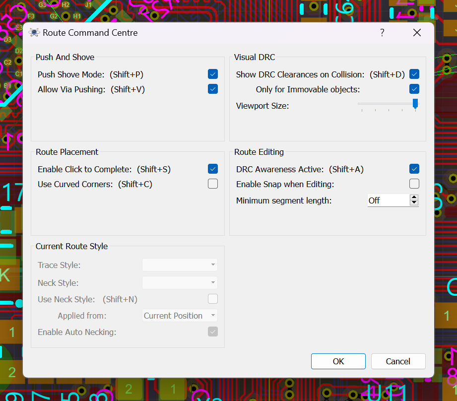
Route Command Centre (Keyboard Shortcut 'R') is the place to configure manual routing options.
Shortcuts
| Keyboard | Action |
| Left Click | Left click while placing a track commits the bit already completed (places an anchor). Also terminates the track at a pin or other connection. |
| Double Click | Places a via at the current mouse location and continue routing on the next layer (as defined in layer pairs dialogue). |
| Right Click | Terminates the track at a point in space. |
| R | Launches the Route Command Centre. |
| SHIFT+P | Toggles between Push Routing Mode and FMR Routing Mode. |
| SHIFT+D | Toggles Visual DRC view on and off. |
| SHIFT+C | Toggles corner type between mitred and curved. Currently only enabled in FMR mode (not supported in Push mode). |
| SPACE | Floats a via on the end of the track. You can then move the via to desired location and left click to place. Can also use up/down arrow keys to select the via depth / drill range. |
| ENTER | Auto-complete the route according to the shadow track shown. |
| F2-F4 Keys | Change the snap level. Normally, this is fine at defaults but you probably don't want a really fine snap when terminating tracks as it makes it harder to snap to centre of pin. |
We will start by routing the SPI lines first. These will of course start and end on the top-copper by the component pins, however we will immediately drill them down onto the inner layers and do the majority of routing there for impedance control reasons (using primarily Inner 2 but jumping to Inner 1 when necessary).
Start by selecting track mode at the left hand side of the Object Selector and changing the layer selector to be on Top Copper.
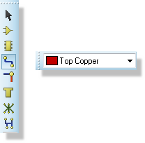
Trace / Track selection and the Layer selector
We'll start with the MOSI line, which is between pin 17 of the MCU and pin 14 of the IMU.
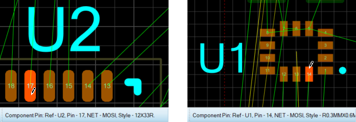
Track ("MOSI" net) will go from pin 17 of the MCU to pin 14 of the IMU
Regardless of the routing mode Proteus features a sophisticated routing algorithm for manual routing in which the route being placed will follow the path of the mouse as best it can while still obeying all of the design rules for the board that we set up previously.
To start the track, click on Pad 17 of the MCU; then move the mouse upwards to start directing the track. As soon as we start the track the status bar changes to show the current routing mode along with the route length and other useful information.
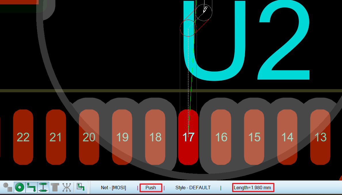
You'll also notice an enlarged circle around the mouse pointer. This is called Visual DRC and will show you the design rule clearances of all obstacles inside the circle - really helpful in plotting your route path across the board.
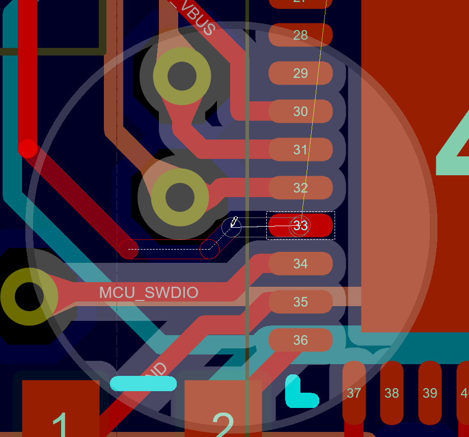
There are also a few other changes to the display to assist with routing:
- All other ratsnest lines disappear and only the one(s) relevant to our current track remain(s) visible.
- Component pins and tracks which belong to the current net are highlighted, whilst all others are dulled.
- A white line (with an arrow if far enough away) appears going from the mouse pointer to the nearest valid component pin which we can connect to, and that pin is highlighted with a white dotted border. If the pin is on a different layer than the joining line appears dashed, and the pin is not highlighted with the dotted border.
- If "Click to complete" is turned on then a ghost "auto-complete" track appears; the "auto-complete" can be accepted by pressing the ENTER key.
Note that we can still zoom in and out whilst routing, and that if the mouse gets close to the edge of the editing area whilst routing then the view automatically pans in that direction.
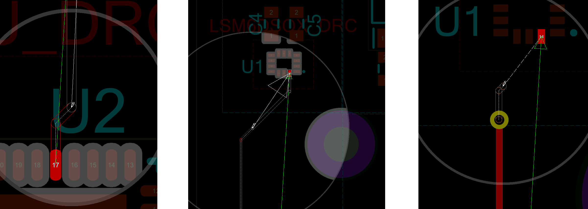
Display interface whilst routing
The track generally follows the mouse pointer and hugs around obstacles, honouring the specified DRC clearances. In push mode (the default) we can move other tracks and vias out of the way if necessary, whereas in FMR mode (SHIFT+P to toggle) all objects are obstacles for hugging. Anchor points can be placed by left-clicking - when an anchor point is placed then the track is "committed" up to that point and display thereof changes from an outline to a solid fill (to un-commit again simply drag the mouse back over the committed section). Vias can be placed (whilst routing) by double-clicking, pressing the Spacebar, or using the Page Up / Page Down keys. More details on these points follow below.
To continue with our routing (having clicked on pin 17 of the MCU to start our route), move the mouse up a little distance and then double-click to place a via. The layer selection should automatically change to "Inner 2", as per our Layer Pairs setup.
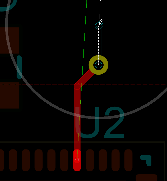
Placing a via to the Inner 2 layer
Move the mouse up near pin 14 of the IMU and then use the Page Up / Page Down keys to prepare a via which will jump to the Top Copper layer. We cannot use the double-click or Spacebar shortcuts in this case as the default layer pair partner for Inner 2 is Inner 1 rather than Top Copper.
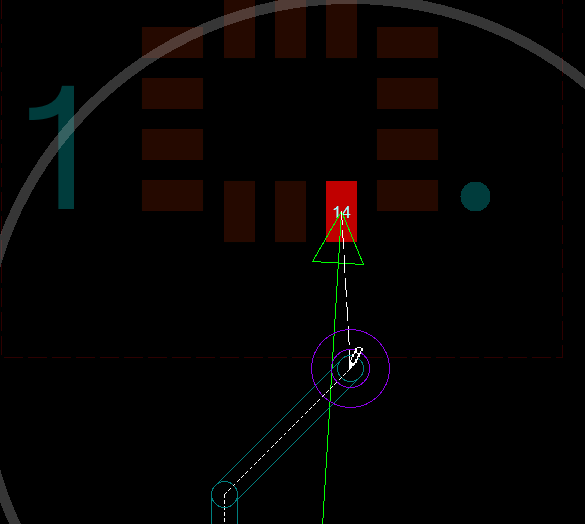
Placing a via back to the Top Copper layer
Click to place the via, and then move the mouse onto pin 14 of the IMU and click again to complete the route.
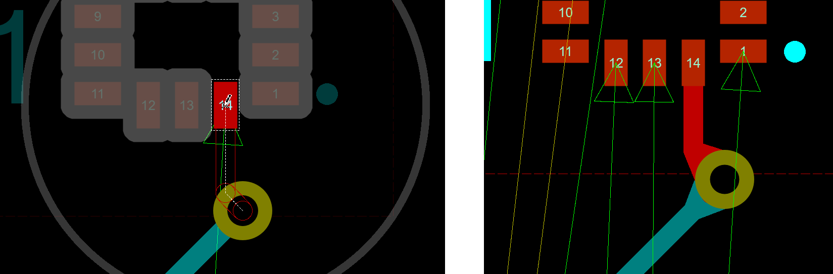
Completing the route
That's it! We've completed the route.
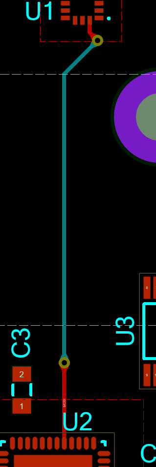
Completed Route
Manual routing is probably the most common action you will perform with the software and it is vital that you understand how it works. The basic rules of operation are :
- Left click on pad, track or zone border to begin routing from that object.
- SHIFT+P key toggles between push mode and FMR mode. Status bar tells you which you are in.
- Left click at any point during routing to commit the route up to the mouse position (we call this anchoring).
- Right click to terminate the route at it's last committed / anchored point.
- ESCAPE key to abandon route entry completely.
- ENTER key will automatically complete the track in the path shown by the 'shadow' track.
- SPACEBAR to float a via on the end of the route and left click to then place the floating via.
- Double left click to drop a via at the current mouse position.
- Move the mouse backwards over existing tracking to rub-out.
- SHIFT+N key toggles the neck style on/off.
- SHIFT+C key toggles curved tracking mode on/off (only available in FMR mode).
- R key launches Route Command Centre to configure routing modes and styles.
Route Command Centre
Route command centre is a central dialogue form which offers full control of routing modes and styles. It can be launched using the R keyboard shortcut at any time - including in the middle of placing a route.
The top left section deals with route placement modes. Some options are then specific to the mode - for example, you can decide whether to disable via pushing but only when you are in push mode. Similarly, you can choose to route with curved corners but only when in FMR mode.
The bottom left section then allows you make mid-route changes to the routing style and necking style. These fields are only enabled when you launch Route Command Centre while placing a route. If you launch from the Tools Menu or via the keyboard shortcut when not routing they will be disabled. This is because track and via styles come from the net class setup and changing during route placement is to allow exceptions to the net class defaults.
The bottom section on the right deals with route editing and enables design rule aware route editing. This is super helpful when tidying up tracks and safely making space on the board and should be left on unless there's good reason to disable.
Finally, the top right section lets you adjust the size of the Visual DRC circle, turn it off completely or enable it for all objects instead of only immovable objects. The latter option is a little subtle because it depends what mode you are in. In push mode, most tracks and vias can be pushed and are therefore not immovable. This is normally helpful because you can see at a glance both where you cannot go (immovable with DRC clearance) and where you can force your way (pushable objects). In FMR mode, all objects are immovable and therefore always show their clearances.
You'll find detailed help on all of the fields in the dialogue level help accessed by the question mark icon at the top right of the dialogue form.
See Also:
We strongly recommend experimenting with manual routing for a while on this board until you are comfortable with how it works in both main modes. You'll probably find that initially you use Route Command Centre to make changes to routing modes but over time you learn the main keyboard shortcuts and then use them directly. The following is a summary of how to perform common actions; try these while routing any of the remaining connections.
Switching Modes
Switch between push mode and FMR mode using SHIFT+P and verify on status bar which mode you are in. Push mode will be your primary tool but FMR mode may occasionally be useful as well.
Panning and Zooming
While placing a track you can use the middle mouse wheel (or F6 & F7 keys) to zoom in and out during routing. Panning will happen seamlessly when the mouse is at the edge of the Editing window during routing.
Placing Anchors
The routing algorithm will move the track being placed according to the way you move the mouse. If you want a track to follow a particular path then you need to help by left clicking whenever you change direction. This places an anchor or commits the route up to the mouse pointer such that the follow me router will not change it. You will see this happening as the outline track becomes solid.
Getting Stuck / Re-routing while routing
Since the manual routing system obeys the design rules for the board you don't need to worry about clearances while placing routes. You can however route to a place where you are blocked (the routing icon will change to a no-go sign at this point). Often you just place a via and continue on but sometimes it is better to rewind and try another path across the current layer.
Moving the mouse backwards over the route being placed will rub out that portion of track so to rewind and change direction just move the mouse back to the last good point - anything you had placed from that point onwards will be removed.
On densely packed boards in particular, speed of mouse movement is an issue. Remember that you are guiding the placement so moving slowly through tight spaces will work far better than ripping the mouse from source to destination. Use the SHIFT+N key to toggle in and out of neck style - this will get you through tight spaces.
Placing Vias
If you double click during placement you will place a via at the point the mouse is at and can then continue routing on the associated layer. If you press the spacebar you will float a via on the end of the mouse and can then position the via manually before placing with a left click. Using the spacebar has the advantage of snapping to legal objects (e.g. via under SMT).
In either case the placement of the via is also design rule aware and the PCB editor will not let you drop a via in an illegal spot. If you use the floating via method (with the spacebar) Proteus will attempt move the via to the nearest legal spot. This can be extremely useful on busy boards or when you want to butt a via tightly against another object.
Layers used for via's are defined in the Layers Pairs dialogue on the Technology Menu. Examples of routing with vias and discussion on layer pairs follows further in the tutorial.
See Also:
Object Hugging
It's often easier to use FMR mode (SHIFT+P to toggle) to hug a track to another track or to wrap a track around an object. If the mouse is over an object where the route being placed cannot travel then the route will follow the mouse path as closely as it legally can, essentially hugging the barrier object.
You can hug in push mode but only if the object you are hugging cannot be pushed !
Abandoning a Route
- If you want to abandon the route at the last committed (solid) segment then right click the mouse.
- If you want to abandon the route at the mouse pointer then left click to commit up to mouse pointer and then right click to terminate the track.
- If you want to abandon the route completely then hit the ESCAPE key..
Making Connections
If you are connecting directly to a pad then a left click of the mouse will complete the connection and terminate route placement.
If you are connecting to a track then left click will commit the placement and right click will terminate the route forming the connection. The same procedure applies if you are connecting to a zone except that you must connect to the zone border.
Route Editing
Next, we will take a look at some options for editing a route after placement. We could of course just delete the whole route and route it again, however it is almost always more advantageous to simply modify the existing route. The right-click context menu provides almost all of the available options for route editing.
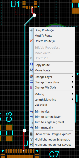
Route right-click context menu
Note that the editing is sensitive to the specific point on the track / section of the track which was clicked. The various "Trim" commands can also be used to limit editing operations to a particular section of track. Take some time to experiment with each of the following commands (as well at the other commands, if you like) - the Undo command (Edit menu / Ctrl + Z) can be used to undo any changes you make. Some of the commands in the context menu, such as Length Matching and Via Shield, will be handled in following sections. Remember that the commands are specific to the particular point on the track / section of track which was clicked, as well as to any selection limitation ("Trim" commands), so you may wish to experiment a few times with some of the commands at different points in the track / with different track selections.
Route Editing by default is design rule aware so you cannot drag a track into an illegal position. This is shown in the status bar during editing and you can toggle DRC awareness off using SHIFT+A or in the Route Command Centre
| Command | Description |
| Drag Route(s) | Drag / move the section of track which was clicked. |
| Modify Route | This command starts routing a new track from the point which was clicked, and continues until you rejoin the existing track; at which point the segment of existing track - between the start and end point of the new modified route - will be deleted. |
| Delete Route(s) | Delete the currently tagged track(s) or section of track. |
| Edit Via Properties... | If right-clicking on a via, then this command launches the "Edit Via" dialogue, which enables changes to via Drill Span, Style and Teardrop. |
| Move Via to... | If right-clicking on a via, then this command launches a dialogue which allows you to specify exact X/Y co-ordinates for the via. |
| Delete Via | If right-clicking on a via, then delete the via. |
| Copy Route | Make a copy of the whole route (or selected section of route). |
| Move Route | Move the whole route (or selected section of route). |
| Change Layer | Change the layer of the selected route(s) / route section(s). |
| Change Trace Style | Change the trace style of the selected route(s) / route sections(s). |
| Change Via Style | Change the style of all vias on the selected route(s) / route section(s). |
| Mitring | Mitre or unmitre square track corners or switch between mitred and curved cornering. |
| Trim to vias | Trim the selection to be bounded by the nearest vias, including the vias themselves. |
| Trim to current layer | Trim the selection to the section of track on the current layer. Similar to "Trim to vias", but does not select the vias themselves. |
| Trim to single segment | Trim to the clicked on straight segment of line. |
| Trim manually | Allows you to then select a second point on the track, and will trim the selection to the section between the two selected points. |
Tracks and vias can also be tagged (selected) when in selection mode, and then dragged or deleted without invoking the right-click context menu. To drag a track simply click and drag it; to delete a track double-right-click on it.
Two of the most common operations, Drag Route and Modify Route, are illustrated in the following screenshots.
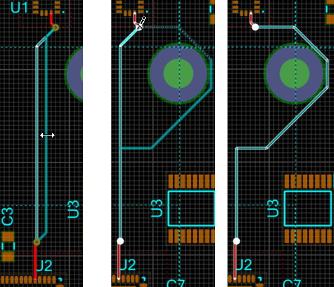
Examples of dragging a route and modifying a route
It is also possible to simply draw a new route or section of route, and then delete the old route / section afterwards.
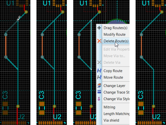
Drawing a new section of route and then deleting the old section
See Also:
Reference Manual: Route Placement & Editing
Reference Manual: Manual Routing Examples
Length Matching
Undo any changes which were made during experimentation (or just redraw the route), so that the MOSI route is again a simple straight connection between the MCU and IMU, with most of the track on the Inner 2 layer. Next, proceed to route the MISO (MCU pin 16 to IMU pin 1), SCK (MCU pin 15 to IMU pin 13) and LSM6D_CS (MCU pin 18 to IMU pin 12) routes in a similar manner. Do a hop to Inner 1 with the SCK line in order to get it over the MOSI and MISO routes. Allow some distance between the tracks, as we will length-match them shortly and will need some space for the length-matching serpentine squiggles.
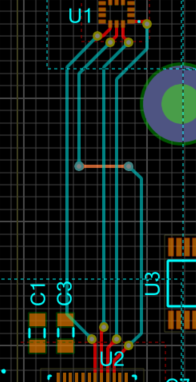
SPI lines routed
We will now length-match the SPI lines (MOSI, MISO, SCK and LSM6D_CS). In order to do this we first need to select the tracks which we would like to length-match: with Selection mode (cursor icon) enabled, click each track once whilst holding down the CTRL key. Then right click on one of the tracks, select "Length Matching" from the context menu, and then "Match route lengths". Move the squiggles, as per the following diagram, by clicking on them and then dragging them to the desired position.
Automatic length matching is part of the advanced feature set and requires PCB Design Level 2 or higher. If you do not have PCB Design Level 2 or higher then simply leave out the length matching (route lengths will stay unmatched).
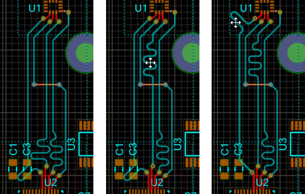
Length matched routes, and moving of the serpentine squiggles
For some more practice, also manually route and length match the MCU_SWDIO and MCU_SWCLK routes.
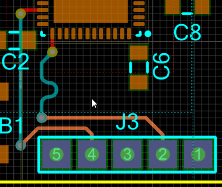
Manually routed, and length matched, MCU_SWDIO and MCU_SWCLK routes
Other points to note about length matching.
- The length of a track is shown on the status bar when it is selected.
- If a track is part of a group that has been length matched the target length is also shown in the status bar when you select the track.
- Routes matched against each other will automatically re-match (where possible) after you edit one route in the group.
- You can see any non-compliant routes in a matchgroup by selecting connectivity highlights icon and filtering the object selector to length matched nets only.
- The pre-production check will test all matched tracks against their target length and warn you if their length has changed.
- If you choose routes with vias the length (depth) of the via is calculated from the thickness values you enter in the layer stackup.
See Also:
Reference Manual: Length Matching Routes
Reference Manual: High Speed Routing Examples
Curved Routes
IRC Placing a route with curved corners can be helpful with signal integrity and net tuning or simply for aesthetic reasons. In Proteus, curved routing is only possible (at the moment) in FMR mode. So,
1) Left Click the mouse to start the route.
2) Check status bar and SHIFT+P to toggle into FMR mode if necessary.
3) SHIFT+C to toggle on curved corners and guide the route towards the destination pad with the mouse.
4) Left click the mouse on the destination pad to terminate the route.
Next, we will route the BlueTooth antenna trace on our board. We will use curved routing in order to maintain constant impedance along the tracks length.
Start a trace, as per normal, from pin 20 of the GSM module.
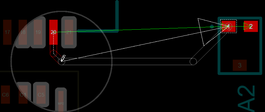
Move the mouse down a little, switch to FMR mode (SHIFT+P - status bar will tell you) and then use SHIFT+C to toggle on curved cornering. Or, press R to enter Route command centre and set up from the dialog form.
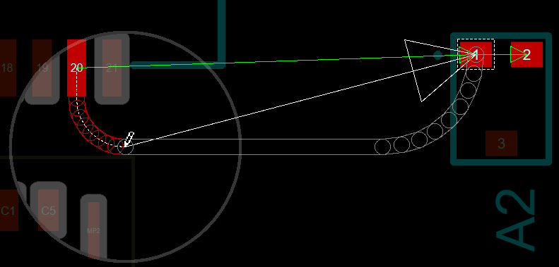
Click to place an anchor point and commit the initial curved section, then continue using the technique to place the remaining sections...
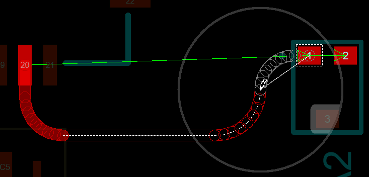
...until the route is completed. You may even wish to take advantage of the track auto-complete option by pressing the ENTER key ("Click to complete" option must be on).
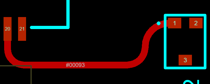
Curved routes can be edited and segments dragged in exactly the same way as linear routes.
Keepout Areas
Keepout Areas can be used to limit areas in which tracks can be placed. We will use some keepout areas to ensure that the impedance of our impedance-sensitive (lenth-matched / RF) tracks are maintained, and not disturbed by other tracks breaking the reference planes beneath / above them. To form a keepout area, start by selecting the 2D Box graphic icon and changing the layer selector to be keepout.
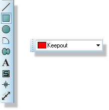
Selecting the Keepout layer
Next, draw a rectangle over the section of the SCK track (between the MCU and IMU) which is on the Inner 2 layer (and which will therefore be referenced to the Top Copper plane, which is as yet to be placed, for impedance-control purposes - again, the SCK track is not really "high-speed", but we are treating it as such for the purposes of this tutorial).
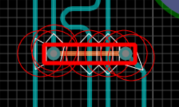
We are immediately presented with a number of DRC errors, as the keepout box defaults to "all layers" and we already have some tracks within it. Right-click on the keepout box and then select Change Layer -> Top Copper from the context menu.
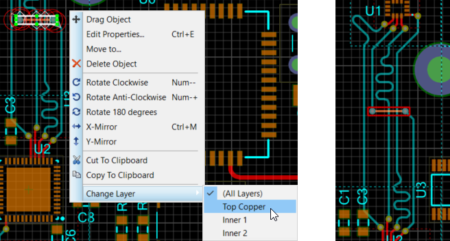
Setting Keepout Layer to Top Copper Only
Also connect the GSM antenna (pin 32 of the GSM module) and draw a Keepout to surround this track, setting the Keepout to apply to layer Inner 1 only.
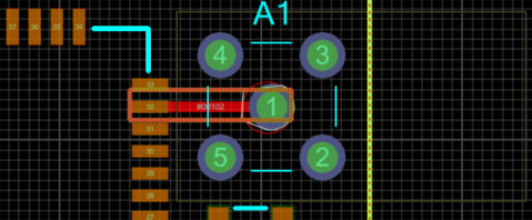
GSM trace and keepout around it on layer Inner 2
Because the GSM antenna pins are through-hole and present on all layers, a DRC error is generated around the GSM antenna centre pin. There are three ways to resolve this error:
1) Make the Keepout box smaller, so that it is not too close to the GSM antenna centre pin.
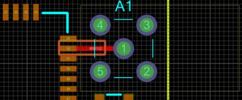
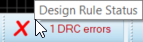
2) Ignore the DRC error: Click on the DRC status bar to bring up the Design Rule Errors window, then right-click on the error and select "Ignore this error".
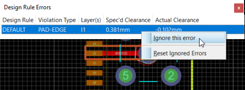
Ignoring a Design Rule Error
3) Place a DRC Room around the GSM Antenna centre pin (setting it to apply to layer Inner 1 only), and then create a Design Rule for that room with "Edge/Slot Clearance" set to "OFF".
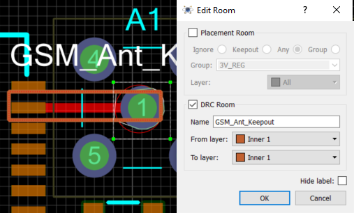
Drawing a DRC Room around the antenna centre pin
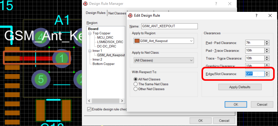
DRC Room rule with Edge/Slot Clearance set to OFF
Option (1) will work fine in this case, so simply make the keepout slightly smaller, avoiding the GSM antenna centre pin.
Also place a keepout under the BlueTooth antenna trace, also applicable to layer Inner 1 only.
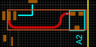
BlueTooth antenna trace keepout (applicable to layer Inner 1 only)
Differential Pair Routing
Differential pair routing is part of the advanced feature set and requires PCB Design Level 2 or higher. If you do not have PCB Design Level 2 or higher then simply skip this section.
We have one differential pair to route on our board, the USB D+/D- differential pair.
Start by breaking out the relevant pins down to vias, so that we will be able to route the differential pair on the Inner 2 layer. Breakout the D+/D- pins on both the microUSB connector as well as on the MCU, as per the following screenshots.
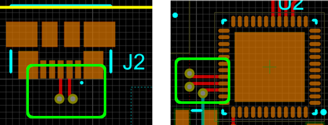
Breakouts, in preparation for differential pair routing, from microUSB connector and MCU
Next, select Differential Pair mode and the Inner 2 layer.
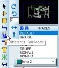
Differential Pair mode and layer Inner 2
We can start the differential pair at either the microUSB connector or the MCU, but for this tutorial we will start it at the microUSB connector. Start by clicking on either of the breakout vias by the microUSB connector. At this point things are just like manually routing any other track. Move down a little and place an anchor point, before moving diagonally down and to the left.
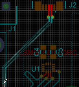
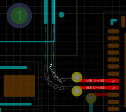
Continue down to the MCU and place a curved section of track before joining to the MCU breakout vias (as before, FMR mode and SHIFT+C for curved corner).
Once completed you will notice that serpentine sqiggles were automatically added at any corners in the track, in order to re-match the phase of the tracks.
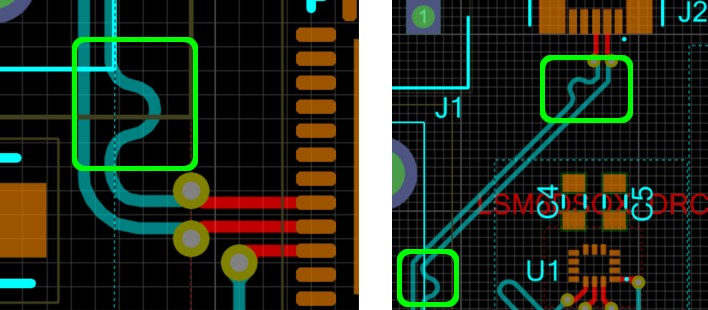
Serpentine squiggles added to re-match the phase of the tracks
If we would like to see the phase sync along the length of the differential pair then this can be done using the "Display phase-offset" feature.
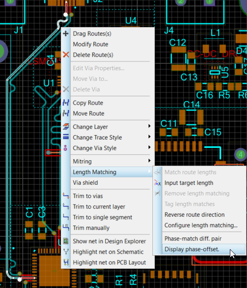
"Display phase-offset" command
In phase-offset display mode; green represents sections of track which are in-phase, yellow represents sections of track where the phase-shift is 50% or more of the specified maximum (as per the Design Rules), red represents sections of track where the phase-shift is 100% or more of the specified maximum, and brown represents section of track where the phase is being re-matched.
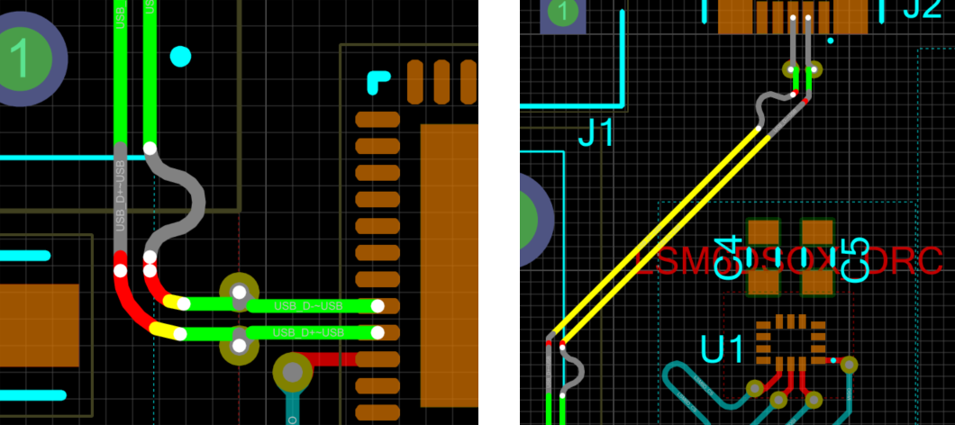
Phase offset display mode
You can use differential pair routing in push mode and it will work just fine (pushing other objects in the same was a single track) but curved cornering is currently only supported in FMR mode.
See Also:
Reference Manual : Differential Pairs
Basic Auto-Routing
You can load the "IoT Pump - HS Routed" sample design in order to continue from this point, if you have not already successfully completed the previous sections.
We will now use the auto-router to complete most of the remaining routes. As with the manual tracking, the auto-router will obey design rules that we configured earlier.
Start by invoking the auto-router from the Tools Menu or from the icon at the top of the application.
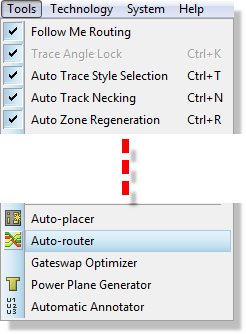
Select the Autorouter from the Tools menu
The resulting dialogue form is reasonably complex but all fields have detailed descriptions available when clicking on the help (?) icon on the top right of the window. You can also find additional information about the various types of routing pass in the reference manual. For our purposes (and indeed for most boards of small/medium complexity) the defaults are adequate. We’ll start by running in ‘fully automated mode’, which should be selected by default, so simply hit the begin routing button to start the autorouting process.
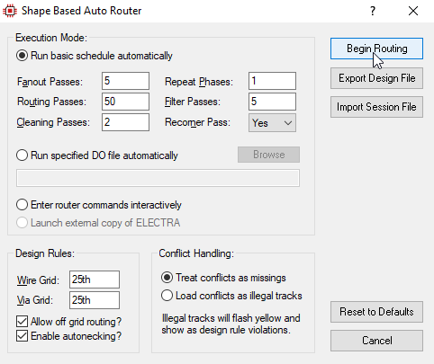
The Autorouter dialogue form
If you see a warning regarding class-class design rules, then it is fine to just click "OK" - if there are any DRC errors present after the autorouting process then these can simply be manually corrected.
Everything will happen quite quickly from this point onwards but you should see routing progress on the status bar as the engine works towards completion. Once the auto-routing process is complete there are two immediate points of note:
- The auto-router has preserved those tracks that we placed manually and has not ripped and replaced them whilst working on the rest of the board.
- Once the autorouter has completed, a final pass is made to corner the tracks. If you prefer this not to happen you can remove the Recorner Pass option on the dialogue form before invoking the router
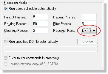
Seting the Recorner Pass to be "No"
Depending on the exact positioning of components, the autorouter may not complete all connections under the "basic schedule", and you may need to manually complete these using the techniques learned earlier. We will take a look at advanced autorouting techniques next however, so you may wish to leave manual routing / tidying till after that section. If any DRC errors are present on the board, then you may wish to correct these now by moving the relevant tracks / vias.
See Also:
Autorouter : Basic Operation (Reference Manual)
The Selection Filter
We will now spend a little time looking at the techniques for selecting various object types on different layers.
The Selection Filter at the bottom left of the application window is used to determine which objects are available for selection at any given time.

The left most button will determine whether the layer selector is active:
When this is toggled off the selection applies to all layers on the board.
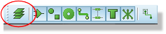
When toggled on the selection applies only to the layer specified in the layer selector.
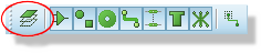
The other buttons represent different object types (tracks, components, graphics, etc.) and determine whether those object types are selectable. Hover the mouse over an icon for a tooltip description.

If you switch between the different modes of operation (for example from selection mode to track mode to component mode) you will see that the selectable object types will change according to the mode you are in. Whilst these are good defaults for normal operation, you can change them at any time simply by toggling on or off the layer switch or object type that you do or do not want to be selectable. If you find yourself changing selectable items regularly then you can also change the defaults via the System Menu – Set Selection Filter command.
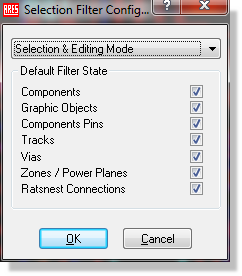
The Layer Selection options
Let’s for example say that we wanted to delete all tracks from the board and start over with routing. Start by entering Selection Mode and left dragging a selection box around the entire board.
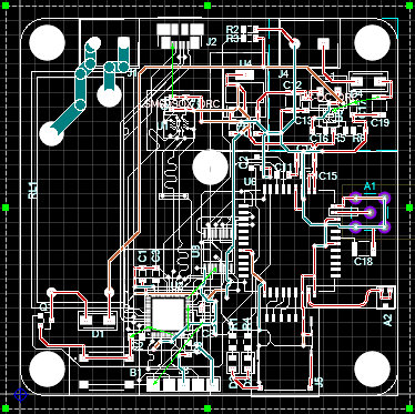
Select the entire board
Next, set the selection filter to exclude those objects that we would not want to delete, namely everything apart from tracks and via’s.

Filter selection to only tracks and vias
The tagged items will update automatically to provide visual confirmation of what is selected.
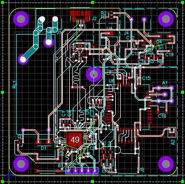
Only tracks and vias selected
At this point we could hit 'Delete', and all the tracks and vias on the board would be deleted. What if we wanted to delete only the tracks and vias around the DC-DC converter, because we wanted to re-route that section of the board? Drag the selection rectangle (using the green handles) so that it only covers the DC-DC converter section of the board.
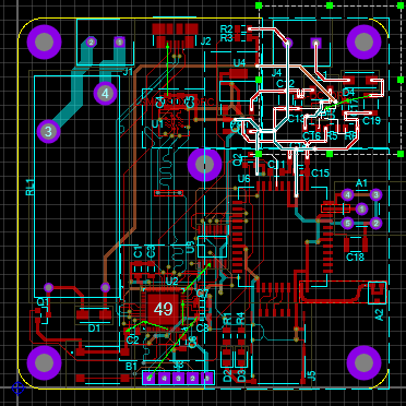
Only tracks and vias around the DC-DC module selected
We now have the option to select tracks which are only partially enclosed by the selection box, or only those which are fully enclosed by it.

Tag box toggle
Switching to "only fully enclosed mode" narrows down the selection further.
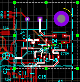
Only fully enclosed tracks selected
We could also select only tracks on a specific layer if we liked, for example only on the Top Copper.

Top copper with single-layer selection mode
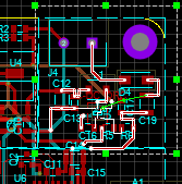
Only top-copper fully-enclosed tracks selected
You may wish to further experiment with the selection filter in order to familiarise yourself with it.
Bear in mind that the selection filter controls what objects
are available for selection at any given time. If you ever find that you
can’t select an item the first thing to check is whether that object type
is enabled for the mode that you are in. Alternatively, simply switch
to Selection Mode where all items are selectable.
Conversely, on a densely populated board, the selection filter can be very
useful for targeting the specific object which you wish to select; remember
that the grid snap setting (View menu) also has an effect on how items
are selected.
Single layer mode is super helpful on a busy board to avoid those accidental
selections of objects on other layers.
Advanced Auto-Routing
Advanced auto-routing is only available in the Professional PCB Design feature set (level 2 and up). If you have one of the lower PCB design levels (Starter Kit, Level 1 or Level 1+) then simply skip this section.
We will now take a look at some of the more advanced auto-routing features, specifically the facility to finely control the auto-routing process.
We will start by re-routing the connections between the GSM module and the TXB0106PWR level shifter. Draw a selection box around these tracks, and delete the tracks.
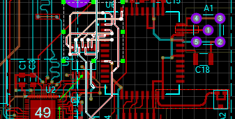
Tracks between GSM module and level-shifter selected
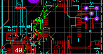
Tracks between GSM module and level-shifter deleted
We will now re-route only these tracks, using the command-driven interactive auto-router. This will allow us to demonstrate the following features of the interactive auto-router:
- The ability to route only a specified area or set of connections.
- The ability to control the routing script; i.e. to determine which routing commands are executed and in which order.
Start by invoking the autorouter dialogue form (Tools Menu), switching to Interactive mode, and then selecting the Begin Routing button.
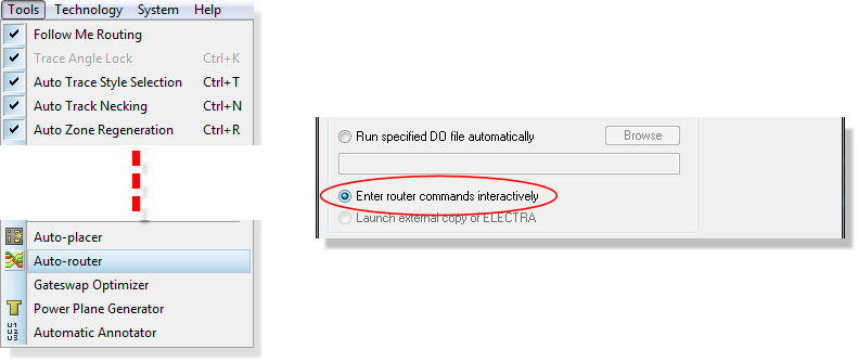
Entering the interactive routine mode
If you see a warning regarding class-class design rules, then it is fine to just click "OK" - if there are any DRC errors present after the autorouting process then these can simply be manually corrected.
A command window will open at the bottom of the Editing Window, which will allow us to direct the routing process interactively. Proteus provides a rich command set to control routing, including such things as bend radius for mitering tracks and fanout length and direction from SMT pads. This is fully documented in the reference manual so we will concentrate on some basic practical examples in this tutorial.
There are a couple of important points worth emphasizing at this stage:
- Any commands entered will action on a set of tagged connections or on the whole board if nothing is highlighted.
- Changing the circuit or switching modes will automatically exit the routing interface.
Essentially, what this means is that we can dictate what connections are routed by controlling which items are highlighted.
The basic syntax of most commands is:
<command> <number of passes>
Start by drawing a box around the area between the GSM module and the level shifter.
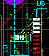
Next type "route 5" in the command box, and press Enter.
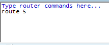
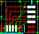
The 4 nets in the selected area will be neatly routed.
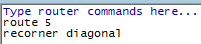
Now execute the command "recorner diagonal".
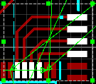
The tracks will be mitred.
Next select the "GSM_STAT_2V8" and "GSM_VDD_EXT" nets, by clicking on their ratsnest lines or any component pads connected to those nets.
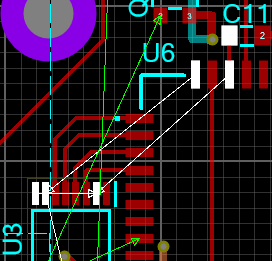
Note that nets can also be tagged by selecting them in the Object Selector and then clicking the "T" button.
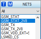
Clicking anywhere in the Editing Window will deselect the currently tagged items. When the focus is in the Editing Window you can also use the middle mouse (or keyboard shortcuts) to zoom in and out in the normal way.
Enter the commands "route 5" and then "recorner diagonal" in order to complete these routes.
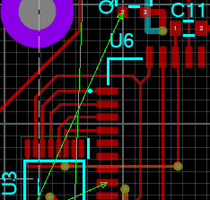
This completes the demo of interactive auto-routing. Do note that there is much more flexibility in the command set than that shown in this tutorial, both in the number of commands and in the parameters that control the command actions.
See Also:
Interactive Auto-Routing (Reference Manual)
Command Reference (Reference Manual)
You can exit auto-routing at any time via the ESCAPE button on your keyboard.
Complete Remaining Routes
Use the techniques already covered in this section (manual routing, route editing, interactive auto-routing) to complete any remaining routes on the board. Once done, you should have No CRC errors and No DRC errors.