GRAPHICS AND TEXT STYLES
Everything drawn on a schematic takes its appearance from a style. A style is a named collection of appearance settings, and every object on the sheet refers to one: a component body is drawn in the COMPONENT graphics style, a component reference such as U1 is drawn in the COMPONENT ID text style, a wire is drawn in the WIRE graphics style. Change the style and every object using it changes with it, which is what makes it possible to restyle a whole schematic from a single dialogue form rather than object by object.
Styles come in two kinds. A global style is held once for the design and is shared by every object that uses it; global styles are edited from the Template menu. A local style belongs to one object and overrides the global style for that object alone; local styles are edited from the object's own properties. Both kinds are stored in the design, and the global styles are also stored in a design template, so that new designs start life with your house appearance already in place.
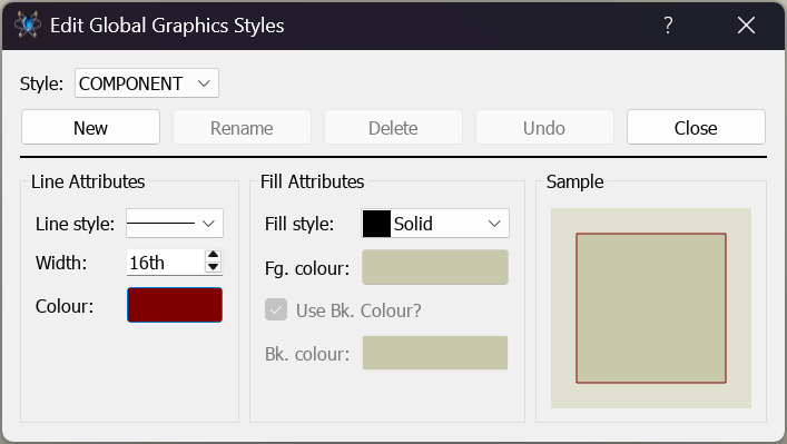
The Edit Global Graphics Styles dialogue form, reached with the Set Graphic Styles command on the Template menu
Global Styles
There are two families of global style. Graphics styles govern the lines and fills used to draw an object; text styles govern the font, size, colour and effects used to draw a label. Each family has its own editor, and the two editors work in the same way: a Style selector lists every style defined for the current design, the attributes of the selected style are shown beneath it, and a Sample panel previews the result.
Six buttons sit under the Style selector in both editors.
- New, creates a style. The new style is initialised from the controls as they stand, so it starts as a copy of the style you were looking at.
- Rename, renames the current style.
- Delete, deletes the current style. Any local style using it as its global style is moved onto the most appropriate system style.
- Undo, discards the edits you have made to the current style. It does not undo a rename or a delete.
- Import, brings in a style definition from another design or template file.
- Close, closes the editor, committing the edits to the current style.
There is no separate apply step. Selecting a different style in the Style selector commits the changes you have just made to the style you were on, and closing the form commits the style you finish on.
The styles listed in the two tables below are predefined system styles, one for each kind of object the schematic draws. They cannot be renamed or deleted, so the Rename and Delete buttons are disabled while one of them is selected. Styles you create yourself carry no such restriction.
Graphics Styles
A graphics style holds a line style, a line width and a line colour, together with a fill style and, for solid and hatched fills, its foreground and background colours. The predefined graphics styles are:
| Style | Governs |
| COMPONENT | The body graphics of a component. |
| PIN | Pins on components and on library parts. |
| PORT | Sub-circuit ports and module ports. |
| MARKER | Markers placed on a library part or on the master sheet. |
| ACTUATOR | The actuator graphics of an active component, such as a switch or a push button. |
| INDICATOR | The indicator graphics of an active component, such as a lamp or an LED. |
| VPROBE | Voltage probes. |
| IPROBE | Current probes. |
| TAPE | Tape recorder objects. |
| GENERATOR | Generators. |
| TERMINAL | Terminals of every type. |
| SUBCIRCUIT | The body of a sub-circuit. |
| 2D GRAPHIC | 2D graphics objects: lines, boxes, circles, arcs, paths and imported images. |
| WIRE DOT | Junction dots. |
| WIRE | Wires. |
| BUS WIRE | Buses. |
The editor is opened with the Set Graphic Styles command on the Template menu, and its window is titled Edit Global Graphics Styles.
See Also:
Set Graphic Styles, for the controls on the dialogue form.
Text Styles
A text style holds a font face, a character height and width, a colour and a set of effects: Bold, Italic, Underline, Strikeout and Visible. Clearing Visible hides every label drawn in the style, which is the usual way to take pin numbers or property text off a drawing. The character width applies only to text drawn in the vector font, since a TrueType face sets its own character widths.
Two font faces always appear at the top of any font list in the schematic, above the TrueType faces installed on the machine.
- Default Font, a placeholder for whichever face is currently chosen as the design default. Styles set to Default Font all change together when you change that one setting, so it is worth using wherever you have no reason to pin a particular face.
- Vector Font, the internal Labcenter vector font. It plots at exactly the same size on every output device as it appears on screen, which a TrueType face does not always do, and it is the face used by the plotter driver whatever the drawing says.
The predefined text styles are:
| Style | Governs |
| COMPONENT ID | Component references, such as U1 or R1. |
| COMPONENT VALUE | Component values. |
| PROPERTIES | Other object properties displayed on the schematic. |
| TERMINAL LABEL | Terminal labels. |
| WIRE LABEL | Wire and bus labels. |
| SUBCKT ID | The instance name of a sub-circuit. |
| SUBCKT NAME | The name of the circuit a sub-circuit is bound to. |
| SCRIPT | The text of a script block. |
| PIN NAME | Pin names. |
| PIN NUMBER | Pin numbers. |
| VPROBE LABEL | Voltage probe labels. |
| IPROBE LABEL | Current probe labels. |
| GENERATOR LABEL | Generator labels. |
| TAPE LABEL | Tape recorder labels. |
| ACTIVE READOUT | The readout text of an active component. |
| ACTIVE REGION | The caption drawn on an active popup window. |
The editor is opened with the Set Text Styles command on the Template menu, and its window is titled Edit Global Text Styles.
See Also:
Set Text Styles, for the controls on the dialogue form.
Local Styles and the Follow Global Mechanism
A local style lets one object depart from the global style without disturbing anything else. You reach it through the object itself rather than through the Template menu: open the object's properties and select the Style tab, or, for a 2D graphic, right click the object and choose Edit Properties.
The Style tab is laid out the same way for text and for graphics. A Global Style selector at the top names the style this object follows, the style attributes are listed down the left, and each attribute has a Follow Global? checkbox beside it.
- While Follow Global? is checked, the attribute is taken from the global style named in the Global Style selector and its control is disabled. Edit the global style later and this object follows the change.
- Clear Follow Global? and the control is enabled, letting you set a value for this object alone. That value is now fixed: later edits to the global style no longer reach this attribute, although every attribute still following the global style continues to track it.
The two are independent attribute by attribute, so a label can take its colour locally while still following the global style for its font, height and effects. A Follow Global? checkbox is disabled where the attribute is meaningless for the current settings, which is why character width cannot be set locally on a TrueType face.
Local graphic styles add two things. A checkbox reading Lock controls to global style's current settings? disables the controls whose settings the global style has made irrelevant, and the form closes with a choice of two buttons: This Graphic Only applies the local style to the object you opened, while All Tagged Graphics applies it to every tagged graphic, which is the quickest way to restyle a whole block of drawing.
Local styles are a property of the object, not of the design, so they are not carried into a design template. If you want an appearance change to reach future designs, make it as a global style change.
Local styles are best kept for the cases that need them, most often 2D graphics on a new library part where some feature must always look the same, such as the solid base of a transistor. Used more widely they defeat the point of the style system, because a part with local styles will not take on the colour scheme of the design it is placed in.
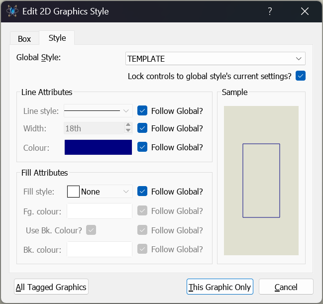
The Style tab of a label editor, showing the Global Style selector and the Follow Global? checkbox beside each attribute
See Also:
Edit Wire Label Style, for the controls on the Style tab of a label editor.
Edit Box/Circle/Path Graphics, for the controls on a local graphics style form.
Design Defaults and Other Appearance Settings
Styles cover the objects you draw. The rest of the schematic's appearance is set by four further commands on the Template menu, and their settings travel with a design template in exactly the same way that styles do.
Set Design Defaults
Sets the colours of the working environment rather than of any object: paper, grid, work area box, world box, highlight and drag colours, the six wire animation colours, and the colour used to show hidden objects. It also holds the Show hidden text? and Show hidden pins? switches, the Font Face for Default Font setting that every style set to Default Font follows, and the Render Master Sheet? switch. The dialogue form is titled Edit Design Defaults.
Show hidden text?, Show hidden pins? and the default font face all travel in a design template, so they behave as design settings rather than as personal preferences. Render Master Sheet? is the exception: it is an application setting belonging to the installation, and is not carried in a template you share.
Set 2D Graphics Defaults
Sets the font face, justification, effects and character sizes given to newly placed 2D graphics text. These are initial values for new objects, so changing them does not restyle text you have already placed. The dialogue form is titled Set 2D Graphics Initialisation.
Set Junction Dot Style
Sets the size of wire junction dots and their shape, which may be square, round or diamond. The colour and fill of a dot come from the WIRE DOT graphics style, not from this form.
Set Graph & Trace Colours
Sets the colours used to draw graphs and the traces on them. Graph and trace colours travel in a design template alongside the styles, which is worth knowing if you are handing a template to a colleague and expect their graphs to match yours.
See Also:
Styles and the Design Template
Style edits change the design you are working on and nothing else. To make them your starting point for future work, save the design as a template with the Save Design as Template command at the foot of the Template menu. The template records the graphics and text styles you have defined together with every setting described above, and the master sheet.
The inverse command, Apply Styles From Template, takes an existing design and puts a template's appearance onto it. It reads the graphics and text styles, the design defaults, the 2D graphics text defaults, the junction dot style and the graph and trace colours, and applies them to the current design.
Apply Styles From Template brings across the appearance settings only. The template's master sheet is not imported, and the sheet size of your design is left as it is. If you want the master sheet as well, start a new project from the template instead.
See Also:
Templates Tutorial, for a worked example of editing global and local styles.