BASIC SKILLS
Interactive simulation is available on every licence. Graph based simulation, and the analysis types that go with it, require the Advanced Simulation Features module.
The Animation Control Panel

The Animation Control Panel
Interactive simulations are controlled from a simple panel which behaves much like the remote control of a video player. The panel is the Animation toolbar and it sits at the bottom left of the window by default. It is there whenever the schematic is open, so there is nothing to switch on first, and if you drag it to another edge Proteus remembers the new position and restores it the next time you run a simulation.
Four buttons control the flow of the simulation, two more launch the system instruments, and a message counter at the right hand end reports what the simulator has to say. The Stop button and the two instrument buttons become available once a simulation is loaded.
- Run starts the simulator and lets the simulation run on continuously.
- Advance moves the simulation forward by the single step time and then leaves it paused. The single step time increment may be adjusted on the Animated Circuits Configuration dialogue, which is opened with the Set Animation Options command on the System menu. Stepping is useful for monitoring the circuit more closely and for seeing in slow motion what is affecting what.
- Pause suspends the animation, which can then be resumed either by clicking Pause again, or stepped on by clicking Advance. The simulator will also enter the paused state if a breakpoint is encountered. Clicking Pause while the simulation is stopped starts it up at time zero, so that the circuit is initialised and any processor boots, but no simulation time has yet elapsed.
- Stop tells PROSPICE to stop doing a real time simulation. All animation is stopped and the simulator is unloaded from memory. All the indicators are reset to their inactive states but the actuators (switches and the like) retain their existing settings.
- Multimeter opens the System Meter, a virtual multimeter which reads the live circuit without your having to place anything on the schematic.
- Scope opens the System Scope, an oscilloscope which likewise needs no schematic component and whose probes can be moved to new signals while the simulation runs.
- The message counter shows a running count of the messages logged by the simulation, and its icon and colour follow the most severe message present, so that errors and warnings are visible without opening anything. Click it to display the simulation log.
See Also:
The System Scope and System Meter
The Simulation Advisor, which is where the messages are displayed.
The simulation can also be controlled from the keyboard. The PAUSE key pauses the simulation and SHIFT+PAUSE stops it. The equivalent commands on the Debug menu carry their own shortcuts, F12 to run the simulation and CTRL+F12 to start a debugging session.
When the simulation pauses, everything pauses. Simulation time stops advancing, so capacitors hold their charge, motors hold their position and clocks stop where they are. This differs from real hardware, where halting the processor leaves the rest of the circuit running. It means that the values you read while paused are a consistent snapshot of the whole circuit at one instant of simulation time.
You can configure the single step time increment used by the Advance button, that is, the amount of simulation time advanced for every click, on the Animated Circuits Configuration dialogue.
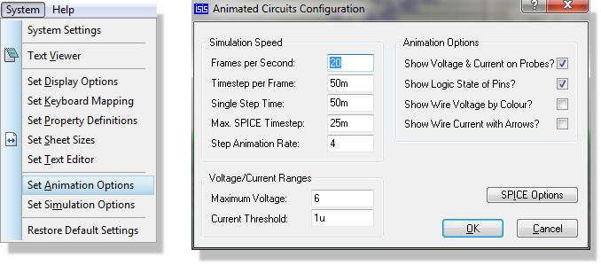
Configuring the single step time for animation
Note that the Advance button on the animation control panel is used for incremental system advances and not for single stepping through code, where specific granularity is required. Debugging code is discussed in detail here.
During an animation, the current simulation time and average CPU loading are displayed on the status bar. If there is insufficient CPU power to run the simulation in real time, the display will read 100% and the simulation time will cease to advance in real time. Aside from this, no harm results from simulating very fast circuits as the system automatically regulates the amount of simulation performed per animation frame. Put another way, the simulation time might not advance with the clock on the wall but everything will still be synchronised and correct.
Indicators and Actuators
Aside from ordinary electronic components, interactive simulations generally make use of special Active Components. These components have a number of graphical states and come in two flavours: Indicators and Actuators. Indicators display a graphical state which changes according to some measured parameter in the circuit, whilst Actuators allow their state to be determined by the user and then modify some characteristic of the circuit.
Actuators are designated by the presence of small red marker symbols which can be clicked with the mouse to operate the control. If you have a mouse with a wheel, you can also operate actuators by pointing at them and rolling the wheel in the appropriate direction.
Setting up an Interactive Simulation
Most of the skills required to set up and run an interactive simulation centre around drawing a circuit in the schematic module. This subject is best grasped by working through the tutorial in the Schematic Capture manual. However, the process will differ depending on whether the simulation includes a microcontroller or not. The basic steps in either case are summarised below.
No Microcontroller
- Create your project, switch to the schematic tab and pick the components you want to use from the device libraries by selecting the Component Mode button and then using the P button on the Object Selector. You can use any component with a simulation model and these parts are indicated at the top right of the schematic preview before the device is selected.
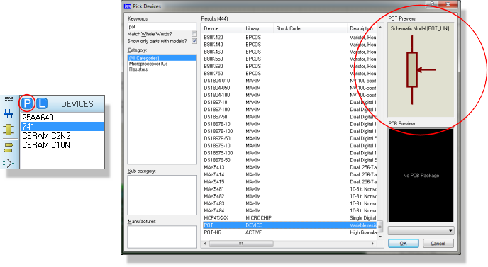
Selecting parts with simulation models via the Library Browser
- Left Click to enter placement mode, move the mouse to the point you want to deposit the component and click left again to commit.
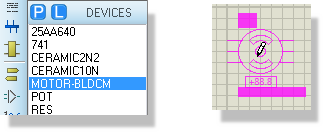
Placing components on the schematic
- Edit them, either by double clicking on the object or by right clicking and selecting Edit Properties from the resulting context menu, in order to assign appropriate values and properties.
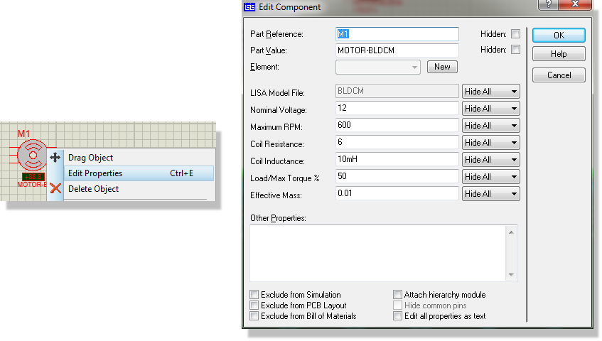
Editing the component properties prior to simulation
Wire the circuit up by clicking on the pins.

Wiring up the schematic
- Delete components by right clicking on the component and selecting Delete from the resulting context menu.
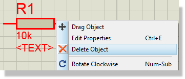
Deleting unwanted components via the context menu
- Move components by clicking left to select and then dragging with the left button.
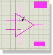
Positioning parts on the schematic
- Click the Pause button on the Animation Control Panel to kick the simulation. This will initialise and boot the simulation but zero simulation time will have elapsed at this point.

Simulation paused
- Where you have used virtual instruments, popup windows related to those components may be displayed using the commands on the Debug menu. These can be configured as desired at this stage, prior to advancing simulation time.
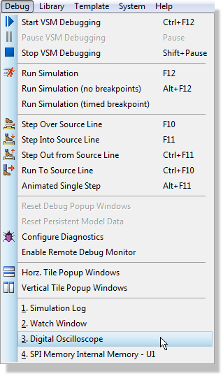
Launching the Oscilloscope Popup from the Debug Menu
- Click the Run button to run the simulation.
With Microcontroller
You can configure a microcontroller project in the New Project Wizard. The full process is detailed separately in a simple tutorial which is linked below. We recommend strongly that you read through this before beginning your own embedded projects.
See Also:
Tutorial : Creating a VSM Project with Source Code.
The alternative to using the VSM Studio IDE is to use your own compilers IDE for firmware development. If you choose to do this then you still need to get the object file into the Proteus simulation after compilation. You can do this simply by assigning the object code file (COF, ELF, HEX etc.) to the microprocessor component on the schematic.
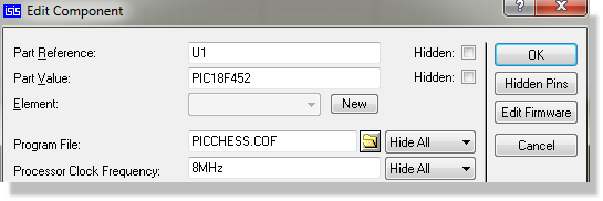
Attaching the source code to the microcontroller manually prior to simulation