MULTI CPU PROJECTS
Introduction
It is quite possible to simulate an embedded system with more than one microcontroller on the schematic with the main limitation being the available processing power of your computer. There are two ways in which you can set up the design of a multi-MCU system and for Proteus VSM the choice largely depends on whether you are making PCBs and, if so, whether the product consists of multiple boards or not.
If each MCU would belong on a different PCB then you should use the multi board setup. On the other hand if you have two MCUs on a single PCB then you can use the single board option.
If working with Arduino or Raspberry Pi or working with Visual Designer then you should use the multi-board approach.
Where one of the boards runs MicroPython, a Raspberry Pi Pico for example, the firmware for that board is written and debugged as described in the MicroPython manual.
Multi Board
Here, each MCU is on its own 'board' in Proteus. The first microcontroller is set up in the firmware tab of the new project wizard. This provides us with a placed component on a sheet and also a skeleton VSM Studio project for the MCU.
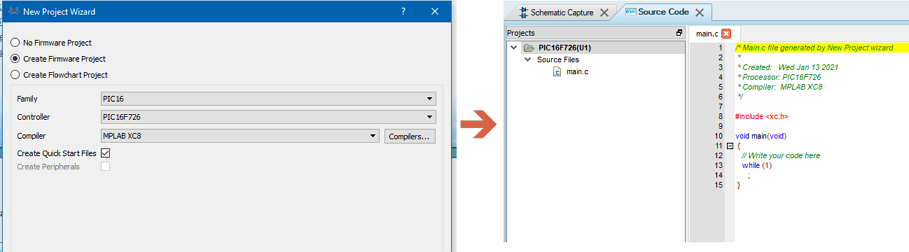
Create the First MCU project in the normal way.
Conceptually, think of this as a single PCB. If your simulated system consists of more than one PCB (e.g. a Raspberry Pi control unit and an Arduino sensor) then a second board is needed. If on the other hand you have two microcontrollers but both are on a single PCB then follow the procedure outlined in the single board topic below.
To add a second board select Create Project from the Project Menu inside the VSM Studio IDE. The neighbouring Delete Project command, on the same menu and on the right click context menu of a project in the project tree, removes a project from the workspace again.
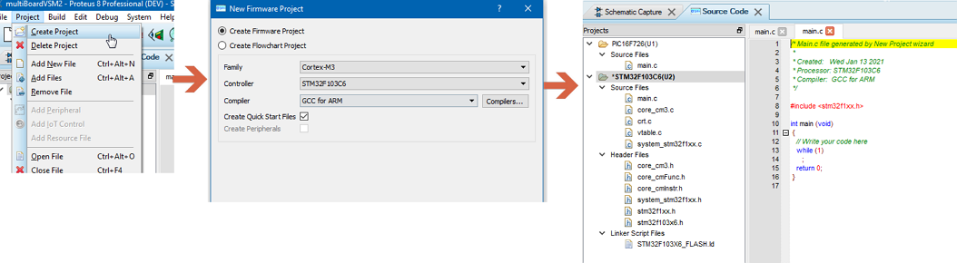
Creating a second CPU project as a second board in Proteus.
At the point you confirm the firmware project wizard you'll get a prompt for the creation of a new board which you should accept.
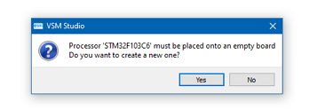
The prompt to create a new board for the second processor.
Once you have created the second project you'll see a new selector at the top of the schematic module which will allow you to switch between the different boards.
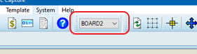
The Board Selector appears on the schematic module.
You can also navigate via the Goto Sheet command on the Design Menu.
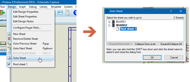
Navigation of a multi board project from the design menu.
You'll probably find it useful to rename the boards and sheets to reflect their purpose. The easiest way to do this is open up the design explorer module and rename them all in the project tree.
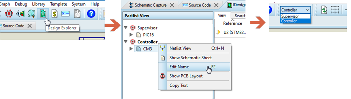
Renaming boards and sheets to keep order.
You can now place and wire to design each board independently, using the board selector to switch between boards as needed. All of the signals and nets will be board local except for the power nets which will be global to the project. Communication between the boards for simulation purposes (e.g. intended via connector) should be managed by making the net project global. You can do this by prefixing the net name on the terminal with the ! character. Design explorer can be used to check the inter board connectivity is valid for simulation purposes.
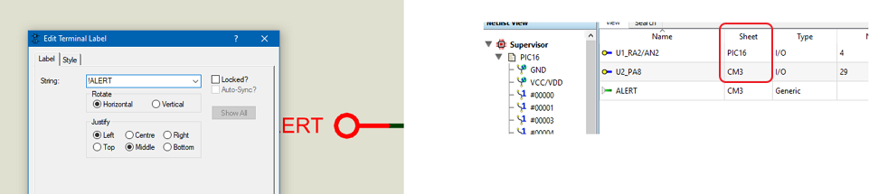
Use the ! prefix on a net to make it global and enable simulated signals across boards.
When simulating / debugging any Active Popups you create from either board will be visible in VSM Studio and a source tab will be present for each MCU. During debugging therefore you can select the firmware of choice and single step through that and the other MCU firmware (along with the rest of the system) will advance synchronously with your debugging session.
Separate variables windows and other debugging windows are also available for each MCU during debugging.
Single Board
This is a situation where you have multiple processors but only one board. You'd start by creating the first project in the usual way (as described above). Next you pick and place the second processor on the same schematic sheet as the first processor. Edit the second processor and select the Edit Firmware option from the resulting dialogue form, exactly as described in the import tutorial.
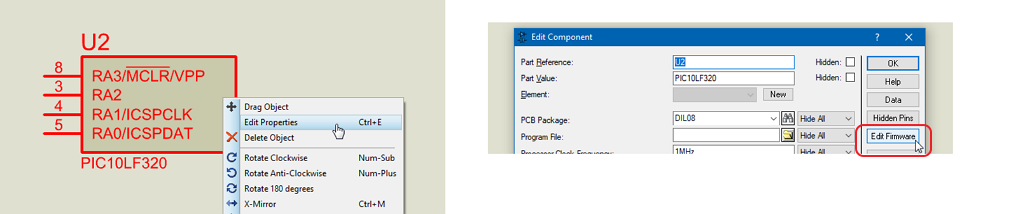
Create a Firmware Project for a second processor on the same board as the first one.
This in turn will switch you to the VSM Studio tab and the firmware project wizard will launch. After configuration is complete you'll end up with a multi-MCU project tree on which the active project will be shown in bold.
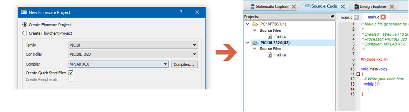
Multi processor support on a single board.
Build Project, Clean Project, Project Settings and the build configuration combo box on the Build toolbar all act on the focused project, which is the one shown in bold. Clicking a project in the tree focuses it, and that is how you choose which of the processors you are building and configuring. Starting the simulation is the exception, since it builds every firmware project in the workspace so that both processors are up to date before the run begins.
After that, parts can be placed on the schematic and wired up to either processor in the normal way. Inter processor communication lines are just wires between the processors on the schematic. A source window tab will be available for each processor during a debugging session as well as a variables window and all of the other debugging views.