HINTS & TIPS
Overview
Most auto-routing exercises proceed along the following lines:
- Load the netlist and place some or all of the components.
- Set up design rules and configure net classes to define track and via styles for routing.
- Organise Plane Layers where appropriate to enable routing to power planes.
- Run the auto-router in fully automated (or scripted) mode.
- Unless complete routing occurs, examine why and where the routing has become congested and move components around accordingly. To remove tracking placed by the router, switch to Track Mode on the mode toolbar and use the Delete button (see Route Placement and Editing).
- When you are satisfied with the component placement, either switch to interactive routing mode for complete control or repeat the fully automatic execution with a higher repeat count.
If you reach 95-99% completion and are struggling to fully complete routing you may want to investigate the problem connections. The easiest way to do this is to use the Connectivity Report on the Tools menu. Double clicking on a list item will zoom the board to that connection, allowing you to easily investigate the problem area.
Apart from the above, the following sections form answers to commonly asked questions about using the auto-router.
Single Sided Boards
To route single sided boards, you need to configure the net classes so that all passes specify the single layer on which you want to route. This will force Proteus to route both horizontal and vertical traces on the underside of the board.
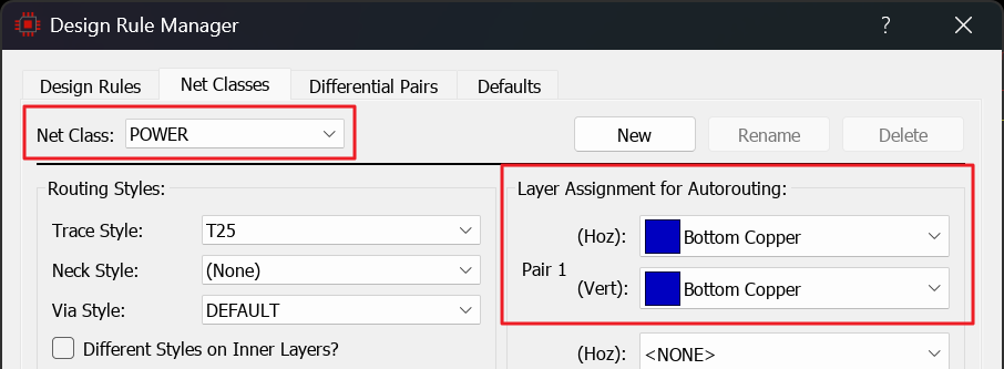
Setting the POWER class to route on a single layer
The number of iterations of the router for single sided boards will be considerably higher than that for boards with multiple signal layers (the removal of via capabilities vastly complicates the routing problem) but, with good component placement, completion of most boards can still be expected.
Routes which are not completed will be left displayed as ratsnest lines; some manual route editing will be required to convert them to be sensible wire links.
Avoiding Using Component Pads as Through Holes
For small scale prototype, hobby or educational production it can be useful to produce boards in which the pins of some components (e.g. ICs, electrolytic capacitors) are not used as through holes.
The way to achieve this is to redefine the component library parts to have pads on the Bottom Copper layer only. The router will then only route to these pads from the underside.
Surface Mount Components
Surface mount components, especially ICs, present something of a problem to a traditional grid based router because the pin spaces are rarely 25 or 50 thou. Thus tracks running on the grid cannot connect directly to the pads because the centres of the grid squares do not coincide with the pad centres.
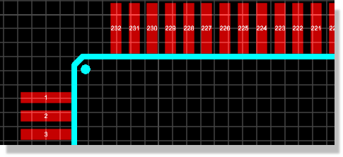
Notice that the centres of some of the pads are not on a grid point: PIN1 is, PIN2 is not
To overcome this, you should always run one or more fanout passes before routing, to make it easier for the router to make connections during the routing phase.
You should also be careful regarding placement of objects such as decoupling capacitors. If you block the entrance to the pads, and particularly if you are routing single sided, then the router clearly cannot make the connection.
Routing to Power Planes
It is important that all power planes to which you wish the auto-router to via to are placed on designated plane layers.
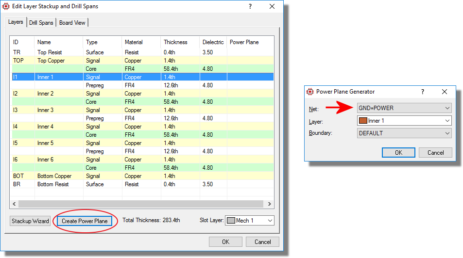
Setting a plane layer.
Despite costing the crossing of a split plane highly, it is possible that a zone is splintered during routing by a track on a different net. This can usually be resolved by adjusting the layer set of a net class or by routing interactively where you have more control. Failing all else it may be necessary to correct this after routing or to simply place the zones after routing in the area concerned is complete.
HDI Boards
If your stackup includes HDI buildup layers with micro-via drill spans, the autorouter will route the board using CNC drill spans only. Laser (micro-via) drill spans are excluded from the autorouter's padstack and are not used for any layer transition. All vias placed by the autorouter will therefore be standard CNC vias with the net class default via style.
When the board contains DRC rooms with micro-via style overrides, a warning is displayed in the autorouter dialogue before routing begins. This reminds you that micro-via styles will not be applied during autorouting and that a post-routing conversion step is needed.
Post-Autoroute Workflow
After autorouting completes, you can convert vias in micro-via regions to the correct styles using the Apply Style button on each DRC room:
- Right click on the DRC room to edit it.
- Ensure the room has the correct micro-via style selected and Use Microvia is ticked.
- Click Apply Style. Proteus will examine each via inside the room and convert those whose drill span matches a valid micro-via transition to the room's nominated style.
- Repeat for each micro-via DRC room on the board.
The Via Inspector provides an alternative way to review and correct via styles in bulk after autorouting. Use the Via Type filter to isolate vias that need attention.
Exclude Foreign Rooms
A DRC room with Exclude Foreign set flags any copper inside it that is not grouped with the room. The autorouter cannot honour that constraint: exclude-foreign rooms are not passed to the router at all, so the router is free to take a foreign net straight through the room and will do so if that is the cheapest path.
Proteus tells you when this applies. If the design contains any exclude-foreign rooms, the autorouter dialogue form displays a warning before routing begins. The pattern to follow is the same as for micro-via rooms: let the router do its work, then check and correct afterwards.
- Route the board as normal.
- Run design rule checking on the finished layout. Any foreign copper the router has taken through an exclusion room is reported as a violation.
- Reroute the offending connections by hand, or use interactive mode to route the affected nets under closer control.
If a sensitive area really must stay clear of foreign copper, it is usually easier to route that region interactively before letting the router loose on the rest of the board, and then protect the tracking you have placed.
See Also: