ROUTE PLACEMENT & EDITING
Overview
The Proteus layout software is equipped with many powerful features to help you place and then edit routes manually. In this topic we are assuming that your project has both a schematic and a layout so that the connectivity defined on the schematic forms the basis for the route placement on the layout.
Pre-Routing Checklist
There are several pre-requisites before you start routing your PCB. You should :
- Have a board edge.
- Define your layer stackup and drill ranges.
- Specify design rules for the board.
- Consider Layer Pairs.
- Consider power planes / zones.
- For HDI boards: create DRC rooms with micro-via style overrides where needed.
Board Edge
You need a board edge to define the size of the PCB that is being made. If you don't place one at the beginning both your component placement and your tracking is likely to need extensive editing later.
Layer Stackup
Defining the layer stackup allows you to specify plane layers directly and also lets you set up drill ranges for vias. Proteus can then use this information when routing to place vias with the most appropriate drill range.
Design Rules
Without design rules, Proteus has no idea how close objects are allowed to be to other objects. When you place tracks manually Proteus will ensure that all the design rule clearances are honoured so it's really important to set them up first.
The net classes tab also lets you set track thicknesses for tracks in the same class (e.g. POWER , SIGNAL, MAINS, ..) as well as via sizes. If you set this up at the beginning then the correct track widths will be selected when you start placing a track.
Layer Pairs
When you are placing a track and you place a via Proteus needs to choose a default destination layer to continue tracking on (e.g. TOP copper -> BOT copper). These defaults are defined in the layer pairs dialogue but if you have multiple signal layers you should review these and make any necessary changes.
Power Planes
If you set up plane layers or manually place power planes early then they will become valid targets for terminating a route. For example, when routing you can double click to place a via. Proteus will know you have a plane layer and (from the stackup / drill ranges) that it can terminate the via and connect. This is a matter of personal choice but can prove a timesaver for things like connecting bypass caps.
DRC Rooms (HDI Boards)
If your board uses an HDI stackup with micro-via drill spans, you should also set up DRC rooms in areas where micro-via routing is required (e.g. over BGA footprints). Micro-via pad styles cannot be specified at the net class level and are instead applied through DRC room via style overrides. Without a DRC room, vias placed on micro-via drill spans will use the standard net class pad style.
If a via is placed inside a micro-via DRC room but the layer transition is incompatible with the room's micro-via style, Proteus displays a one-shot warning on the status bar. The via is still placed using the net class default style so that routing can continue without interruption. See Layer Range Compatibility for details.
Basic Route Entry
Once everything is set up the act of route placement is actually fairly simple. Here is a walkthrough of the basic process.
First, you select track mode and switch to a valid layer.
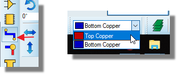
Selecting Trace Mode and a valid copper layer.
Next you left click on the centre of a pad to start a connection.
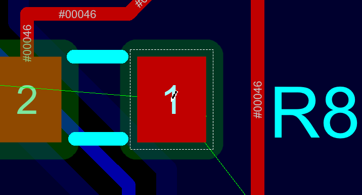
Left clicking on the centre of a pad to start the connection.
You'll notice that if you set up net classes as in the topic above and you have Auto Trace Style Selection enabled from the Tools menu (Ctrl+T) then Proteus will select a track of the correct width automatically when you start routing.
You'll see a guide arrow to the nearest destination if you are on the same layer you will most likely also see a 'shadow track'.
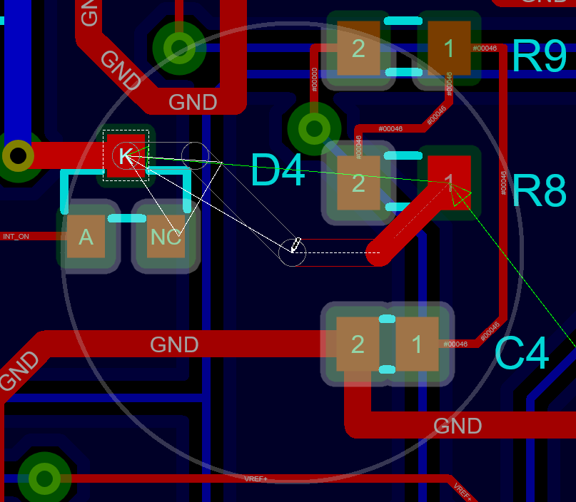
The guide arrow and shadow track shown as routing begins.
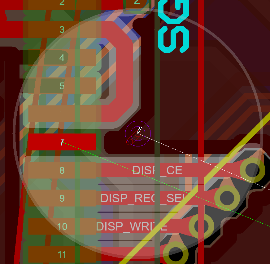
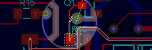
You'll also see a circle around the mouse and objects inside the circle which are obstacles (can't be moved) will be expanded to show their design rule clearances. If you are NOT in Push mode, then you will see that all obstacles will have their DRC area highlighted:
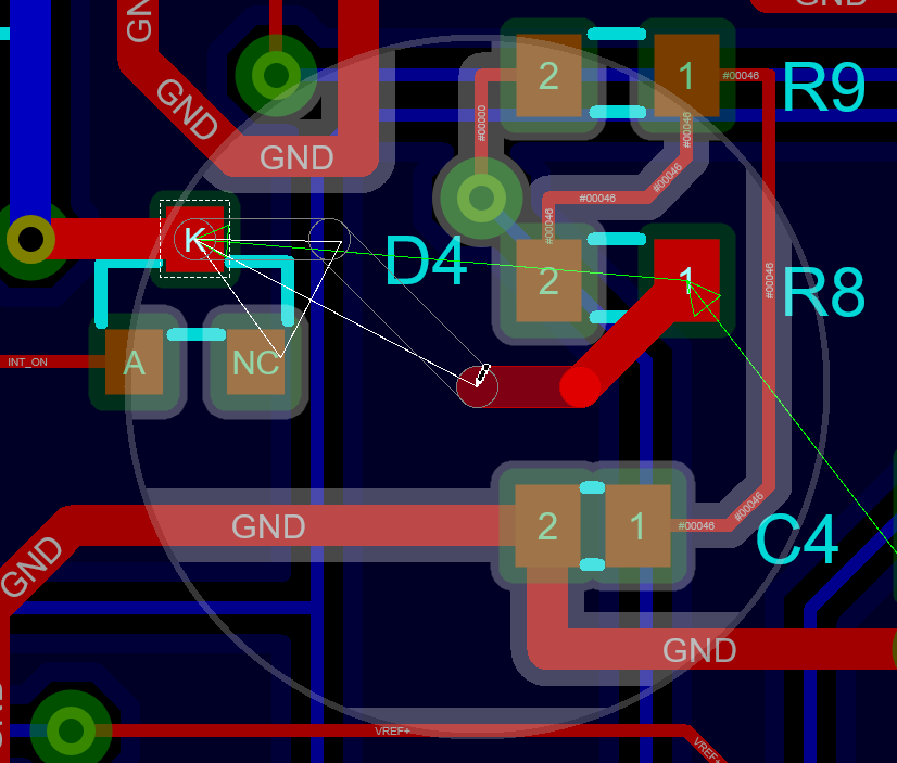
Visual DRC in FMR mode showing the clearances in the area around the mouse.
Visual DRC (by default) shows the clearances around immovable obstacles. What you see will therefore differ in push mode (where some objects can be moved) and FMR mode (where all objects are immovable).
You can either move the mouse to guide the track towards the destination or simply hit the ENTER key to automatically complete the track. In practise you'll find that auto-completing simple tracks is a great timesaver but that you need to give some manual guidance for more complex tracks.
If you need to place a via, press SPACE to place a floating via or double click to place one at the current mouse position. If you want to continue on a layer other than the paired one, use PGUP and PGDN first to cycle the valid layer destinations.
Placing a via part way through a route.
Unless you have cycled the destination with PGUP or PGDN, you will switch to routing on the layer defined in the layer pairs dialogue as discussed in the topic above.
As you route the track it will step away from all the objects according to the design rules.
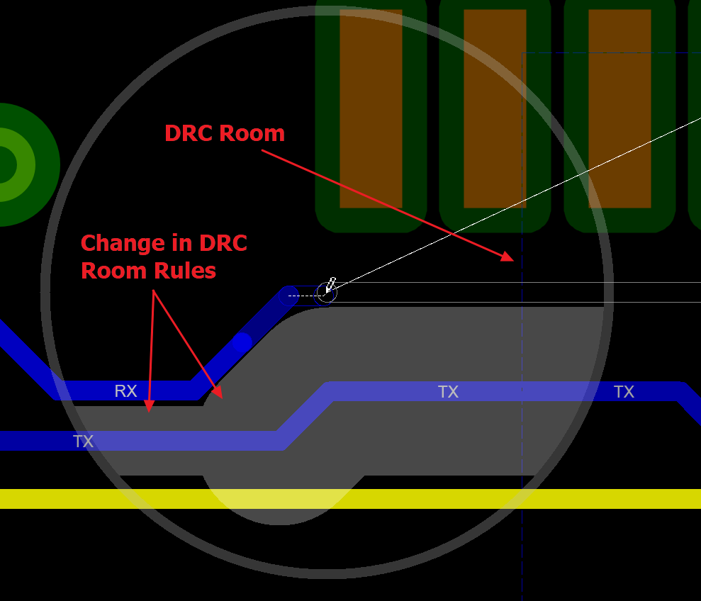
The route stepping away from surrounding objects to honour the design rule clearances.
Left click the mouse at the centre of the destination pin to complete the connection.
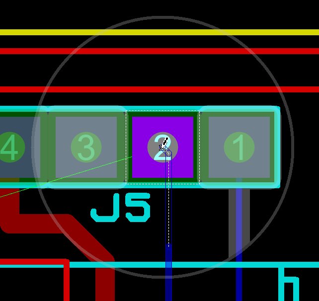
Left clicking at the centre of the destination pin to complete the connection.
Sometimes, if you have switched to a fine snap and you are at high zoom then it's hard to find the pad centre and the snap distance is too small to be of much help. Switch to a higher snap level (e.g. F3) so that Proteus can help snap the mouse to the pad centre.
Push Mode vs FMR Mode
There are two main ways to route in Proteus, namely Push mode and FMR mode. You can toggle the routing mode at any time with the SHIFT+P keyboard shortcut.
Push Mode
This is the default mode and allows you to move tracks and vias out of the way of the route being placed while obeying all design rules. Generally faster and more productive routing as it doesn't involve a lot of manual editing to make space for route placement. Also superior in densely packed regions of the board.
Notes:
- You can't push length matched routes or diff pairs.
- You can't push routes on net <NONE> as otherwise you couldn't connect to them.
- You can choose whether or not to push vias from the Route Command Centre (keyboard 'R').
- Pushing non 45 degree tracks is unlikely to give a sensible result. Pushing quadrant arc curves is fine.
FMR Mode
This is also a fully design rule aware routing mode but will treat all objects as immovable. Useful for hugging tracks and where you want total control over all route topology.
Mode Switching and the Status Bar
You can switch between modes using the SHIFT+P keyboard shortcut. This will work at any time including during route placement, meaning for example that you can start placing a route in push mode and then switch to FMR mode to hug another route. The current routing mode is shown along with other route information on the status bar during route placement.
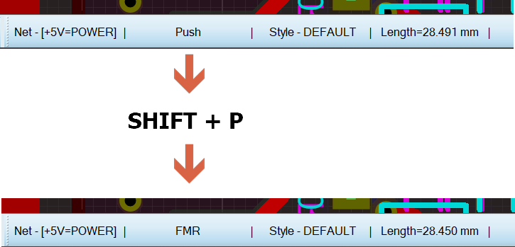
Switching modes displays on the status bar during route placement
Route Command Centre
You can fully configure routing from the route command centre (keyboard shortcut R). This will also work at any time, including in the middle of route placement. This provides another way to change routing modes (although less fast) but also gives you control over what objects are pushed and the size of the Visual DRC display for example.
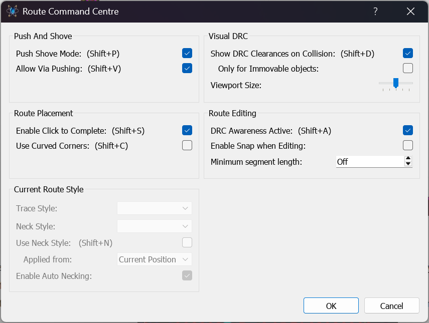
Route Command Centre (Keyboard Shortcut 'R') is the place to configure manual routing options.
See Also:
Troubleshooting / Common Issues
Unconstrained Routing Mode
This routing mode has no knowledge of design rules, net classes or other information. Proteus is blind when you use it so we strongly recommend it is used only when necessary (e.g. an elliptical arc in an antenna design).
There is a third routing mode which we include here for completeness.
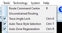
Unconstrained Routing Mode can be turned on from the Tools Menu (Ctrl+U).
Unconstrained routing mode is a legacy routing mode which has no knowledge of design rules and works to a much simpler algorithm. It does however, allow the user to do absolutely anything (with trace angle lock off), including the drawing of elliptical arcs which may be useful in some antenna design for example.
Turning this on will disable the Route Command Centre and all Proteus 'routing intelligence' (notably design rules!). Making any change to Route Command Centre or normal use keyboard shortcuts will disable unconstrained routing mode and switch back into the normal use paradigm as discussed in the rest of this topic. You can also turn it off from the Tools Menu or with Ctrl+U.
Notes:
- This mode does interact with Trace Angle Lock so any angle routes requires the disabling of this feature. Note that such tracks will be difficult to edit subsequently because they will be at arbitrary angles. Remember to turn trace angle lock back on as soon as you are finished !
- Elliptical curves can be drawn in this mode by holding the CTRL button down while routing. Note that normal curved routing is done in FMR mode and is fully DRC aware and compliant. These curves can also be easily edited.
Actions and Hints
There are a number of actions that can affect route placement and also a number of hints that the software provides to help guide route placement. These are discussed below:
Options
These two options govern how the track style is chosen while you route. We'd recommend leaving the defaults unless you have good reason to change.
| Mode | Description |
| Auto Track Necking | Enable the automatic narrowing of the track to the neck style (specified in net classes) in cases where it cannot fit or connect at full width. The control is the Enable Auto Necking checkbox in the Route Command Centre, Current Route Style group, and it is only enabled while a route is being placed. |
| Auto Trace Style Selection (Ctrl+T) | Enable the automatic selection of the track style (width) when route placement begins. The track style is defined in the net classes tab of design rule manager. This is a toggle on the Tools menu. |
Actions
| Keyboard | Action |
| Left Click | Left click while placing a track commits the bit already completed (places an anchor). Also terminates the track at a pin or other connection. |
| Double Click | Places a via at the current mouse location and continue routing on the next layer (as defined in layer pairs dialogue). |
| Right Click | Terminates the track at a point in space. |
| R | Launches the Route Command Centre. |
| SHIFT+P | Toggles between Push Routing Mode and FMR Routing Mode. When editing other tracks and vias will push with Push mode on and be obstacles with push mode off. |
| SHIFT+D | Toggles Visual DRC view on and off. |
| SHIFT+C | Toggles corner type between mitred and curved. |
| SHIFT+V | Toggles via pushing on and off, so that the route being placed or edited can move vias as well as tracks. |
| SHIFT+S | Toggles Click to Complete, the shadow track solution shown ahead of the route, on and off. |
| SHIFT+N | Toggles the current neck style on and off, so that you can neck down through a tight gap and back out again under your own control. |
| PGUP / PGDN | Cycles the valid layer destinations for the route. Use this before placing a via if you want to continue on a layer other than the paired one. |
| SPACE | Places a via at the current position and continues routing on the destination layer. With smart vias enabled the best drill span for the transition is chosen automatically at the end of the route. On HDI boards, the micro-via drill span is used for adjacent layer transitions only when inside a DRC room with a micro-via style override; outside a room the shortest CNC span is selected instead. The via pad style comes from the net class default or, if inside a DRC room, from the room configuration. |
| ENTER | Auto-complete the route according to the shadow track shown. |
| F2-F4 Keys | Change the snap level. Snap level 1, the coarsest, is CTRL+F1. Normally, this is fine at defaults but you probably don't want a really fine snap when terminating tracks as it makes it harder to snap to centre of pin. |
Hints
| Hint | Description |
|
|
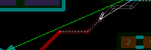
Shows you proposed route from last committed place to the mouse position. Click left to place an anchor and commit or move mouse to adjust. |
|
|
Shows you the track that would be placed if you click ENTER to auto-complete the route. |
|
|
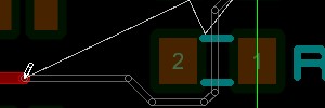
Shows you the path to the nearest connection on the current layer. |
|
|
Shows you the path to the nearest connection on a different layer (there are no possible connections on the current layer). |
|
|
Shows you that the current route position is illegal, or that you are pushing tracks into an obstacle. Try neck style or move mouse to route in a different way. |
|
|
Cursor change and status bar change shows you are pushing more objects than are allowed. Normally this happens when you are also pushing vias which in turn are pushing objects on multiple other layers as well. You can left click to commit track so far and reset the pushed object count or move the mouse backwards and try a different way. You might also look at launching the Route Command Centre (keyboard R) and disable the pushing of vias. |
|
|
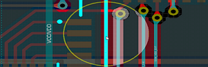
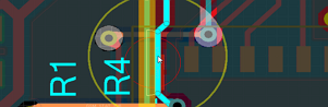
Shows you the design rule clearances of nearby objects (SHIFT+D to toggle). Configurable in Route Command Centre ('R' Shortcut) |
|
|
Shows you that the track being edited has a DRC violation somewhere on its length. Only applicable when DRC Aware Editing is turned off (SHIFT+A to toggle). |
|
|
When the route being dragged gets too close to another object in the viewport it highlights to warn of the violation. Only applicable when DRC Aware Editing is turned off (SHIFT+A to toggle). |
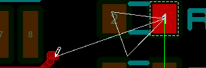
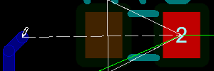
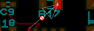
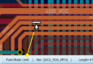
Status Bar
During route placement the net being routed is displayed along with the routing mode, the track style and the current length of the route.
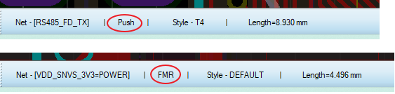
The status bar during route placement, showing the net, routing mode, track style and route length.
If you are pushing more objects than the allowable limit you'll end up not being able to push any further and the Push text will change to reflect that:

The status bar reporting that the push limit has been reached.
Most commonly this will happen when tracks you push are tied to vias because then you'll be pushing the tracks on the other layer as well as the vias and the tracks on the current layer.
If you switch to necking mode the style will update to reflect that and the length will change from the total route length to date to the current length of necked route.

The status bar showing the neck style and the length of necked route.
In diff pair routing mode the status bar is identical except that the net display changes to say 'fatroute', reflecting the fact that two nets are being routed together.

The status bar during differential pair routing, showing fatroute in place of the net name.
When editing routes you also see the live length of the route as it is dragged along with information on the current editing mode.

The status bar during route editing, showing the live route length and the editing mode.
If you try to make an edit which is not possible the status bar will show an error message. This includes the currently set minimum segment length (as per Route Command Centre) as this is often the reason the edit can't complete.

The status bar reporting that the requested route edit is not possible.
If you try to push edit tracks which are at non 45 angles it will not work. Quadrant arc curved mode corners are fine and tracks placed normally are fine but tracks placed in unconstrained routing mode will have any angle properties and the push algorithm will perform poorly.

A track at an arbitrary angle, which the push algorithm cannot edit cleanly.
See Also:
Curved Track Segments
Proteus fully supports curved tracks and supports them as true arcs for output purposes. The segments also play a full role in connectivity and design rule checking. To toggle curved tracks when routing you use the SHIFT+C shortcut key or you can enter the Route Command Centre ('R' keyboard shortcut) and change the settings manually.
Then to place a curved segment, first commence routing as usual (e.g. click left on a pad) and route as normal. Move the mouse roughly to trace the arc, click left to fix the arc endpoint and then continue onward. You can place a curved segment at any stage of laying a route, so it does not have to be the first or last segment.
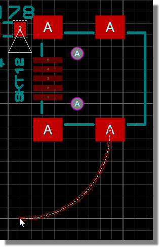
Placing a curved track segment part way through a route.
Curved tracks placed in normal routing will be fully design rule aware and will avoid obstacles in exactly the same way as linear tracks, and they push in exactly the same way too. However, they are limited to circular quadrants; if you need a truly elliptical curve you must first switch to unconstrained routing mode from the Tools Menu (Ctrl+U). Be aware that the trace placement will no longer be aware of board constraints so you'll want to switch back to normal routing (Ctrl+U again, or make any change in the Route Command Centre) when you are finished !
Sometimes it might be better to try routing in push mode and then converting to curves when you are finished placing the route. This can be done from the Mitring sub-menu on the route context menu.
Auto-Track Necking
In many cases, the reason for necking down a track is so that it can pass between two pads or other obstacles without violating the design rules. The Auto Track Necking feature allows Proteus to do this for you.
In order to auto-neck during routing you need to pass through the gap in a straight line (i.e. not at an angle). The track neck will appear once you are more than half way through the gap.
The neck thickness is controlled by the Design Rule Manager command on the Technology menu. The dialogue form allows you to enter the clearances for pad-pad, pad-trace and trace-trace and also the trace style to neck to. By default no neck style is set on a net class, so auto-necking has no effect until you choose one here.
Auto necking is enabled and disabled from the Enable Auto Necking checkbox in the Route Command Centre, in the Current Route Style group. Turning it off can speed up route placement considerably, since the analysis involved in performing ATN can be quite complex, even if the end result is that the route is OK.
When placing a route you can force the use of the neck style with the SHIFT+N toggle, which is the Use the Current Neck Style command. Since this is actioned specifically by the engineer it's pretty much infallible. Left click to anchor, SHIFT+N to toggle neck style on, route as needed, left click to anchor, SHIFT+N to toggle back to normal routing style.
Trace Angle Lock
Trace Angle Lock (Ctrl+K) is enabled by default and cannot be turned off when routing using DRC aware Follow-Me-Routing or Push Routing. Turning Unconstrained Routing on via the Tools menu (Ctrl+U) allows you to then turn off Trace Angle Lock. We would expect this to happen almost never but provide the information below for completeness.
Do not turn this off without good reason. If you have a good reason, turn it back on again as soon as you can. It's an important tool in keeping a tidy, maintainable layout. Push editing will work poorly if at all with non 45 degree angles on tracks.
Most people like to keep all tracking running at either 90 or 45 degrees as this gives a tidy, professional look to a layout. To make this easier, Proteus has a Trace Angle Lock command on the Tools menu (Ctrl+K) which restricts route segments to 90 or 45 degree angles only.
TAL also has a more subtle effect when combined with Real Time Snap. Consider the following routing problem... You are trying to route from a pad on the grid to one that is off it. You have moved down, clicked left and moved the pointer over to the destination pad. Real Time Snap has detected the pad, and the cursor has locked onto it. However, because your first click left was on a grid dot, the horizontal part of the track doesn't line up with the pad centre. The diagram below shows the position at this stage:
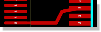
TAL set to 'Off'
When Trace Angle Lock is enabled, clicking over a pad or track in this circumstance will activate Trace Angle Fixup. The result is that the previous node, in this case the route corner, is moved so that trace angle lock rules can be maintained. The result is a tidy connection as shown below.
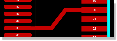
TAL set to 'On'
Tagging a Route
To re route, delete or copy a section of tracking requires that you first tag the route containing it.
To tag a route
- Ensure that the trace selection icon on the Selection Filter is enabled.
- Point at an exposed part of the route on the selected layer, and click right. This will both select the route and present a context menu of appropriate actions that can be performed on the route.
Provided that you are not in trace mode (or put another way, that the mouse cursor is a selection cursor, the pointed hand, when over the trace) you can simply left click to tag the route.
To tag a section of a route
- Ensure that the trace selection icon on the Selection Filter is enabled.
- Point at an exposed part of the route on the selected layer, and click right. This will both select the route and present a context menu of appropriate actions that can be performed on the route.
- Select one of the Trim options from the bottom of the context menu.
If you select Trim Manually then the point at which the mouse was clicked becomes an anchor point and you can move the mouse to the other anchor point, left clicking to select the section of trace between the endpoints.
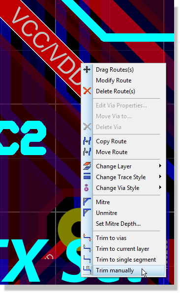
Right click and select 'Trim Manually'
Please note that you cannot select sub-sections of tracking that run through pads, vias or T-junctions using this method.
Changing the Width of a Route
Proteus provides a few methods of changing track width. The first relies simply on the general ability of the layout to cope with new objects being placed over old.
To change the width of a Route during Placement
- Press 'R' to launch the Route Command Centre.
- Change the width from the options provided on the left hand side. Set Applied from to either Current Position or Entire route as appropriate.
- Hit OK and continue routing.
- Repeat as needed.
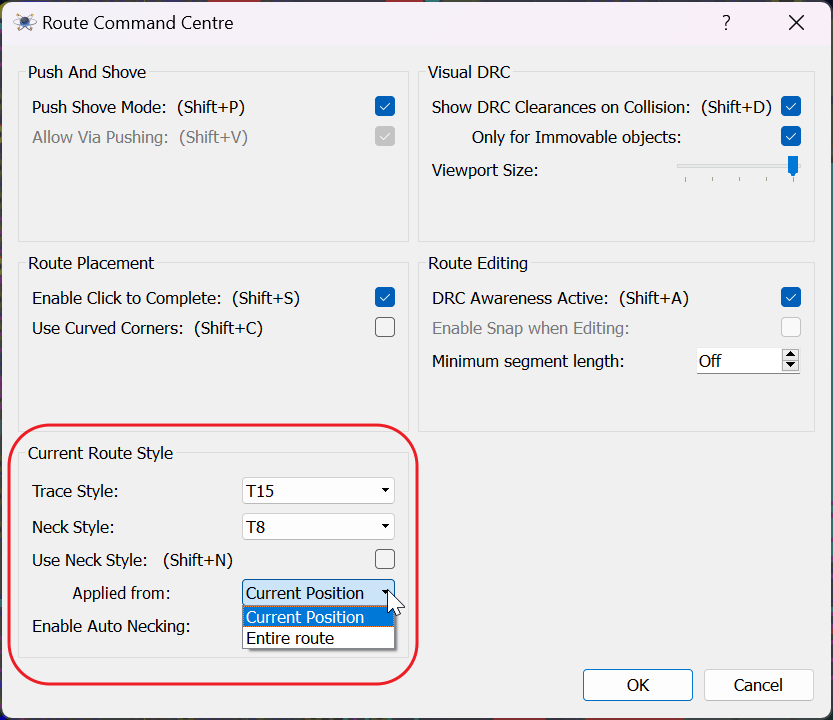
Change the Trace Styles mid-placement via the Route Command Centre.
To change the width of placed tracking by overplacement
- Ensure that there is no tagged route, and that Auto Trace Style Selection is disabled on the Tools menu (Ctrl+T).
- Select the new trace style in the Object Selector.
- Place the new tracking directly over the old. Proteus will work out that there is overplacement, and will replace the old tracking with the new in the database.
The second follows the principle of allowing various editing operations to be performed on the currently tagged object.
To change the width of a tagged section of tracking
- Tag the required section of tracking as described under Tagging a Route. The Object Selector will display the current trace width. If the tagged route has several widths, then the width at the point under the cursor is displayed.
- Click right on the tracking to display the context menu.
- Select a new trace style from the menu.
To change the width of multiple tracks
- Switch to selection mode and then CTRL+left click on tracks to select them.
- Click right on any one of the selected tracks and select a new trace style from the resulting context menu.
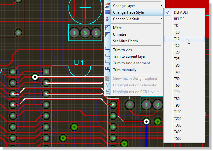
Selecting several tracks with CTRL and left click, then choosing a new trace style from the context menu.
Changing the Layer of a Route
To change the layer of a tagged section of tracking
- Tag the required section of tracking as described under Tagging a Route.
- Click right on the tracking to display the context menu.
- Select a new layer for the tracking from the menu.
To change the layer of multiple routes
- Switch to Selection Mode.
- Adjust the Selection Filter to single layer only.
- Use CTRL+Left Click to select the tracks you want.
- Right click on one of the tracks and select the destination layer from the context menu.
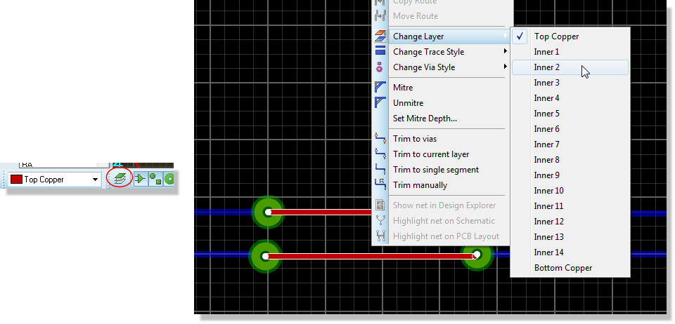
Changing the layer of several selected tracks from the right click context menu.
It is quite easy to makes mistakes such as orphaning tracks or leaving stray vias when changing routing layers. Check carefully after the operation is complete.
Modifying an L45 Route
The goal of route editing generally is to transform the route according to mouse movement while maintaining neat L45 routing. You can if needed turn off Trace Angle Lock and route any angle but in the general case the result will be less tidy and involve more small segments. We'd recommend therefore that unless necessary trace angle lock (Tools menu, Ctrl+K) is kept on for route editing operations.
For multi-track editing where the route being dragged hits another route the rules for route editing behaviour can be broadly summarised as:
- When Design Rule Aware Editing is on (the default) the system knows about other objects on the board and will avoid violations. If you turn this off Proteus is entirely blind and you can edit a track anywhere, including through other tracks and components.
- When Push mode is on (the default) editing tracks will push other tracks out of the way so long as Design Rule Aware Editing is on. When Push mode is toggled off editing tracks will hug other tracks so long as design rule aware editing is on.
The most common usage is likely to be in push mode as that will maximise space on the layout. However, there are times when you want specifically to hug another track and toggling push mode off will do that.
| Shortcut | Action |
| SHIFT+P | Toggles push mode on and off. Note that this setting applies to both route placement and route editing. |
| SHIFT+A | Toggles design rule aware editing on and off. This should only really be turned off if you are in a position where a legal edit is impossible (e.g. you've changed pad->track design rules and existing tracks are in violation). Take care not to press CTRL+A instead, which is the Align Objects command. |
| R | Launches the Route Command Centre where all route options can be found |
To modify an existing track
- Tag the route as described under Tagging a Route.
- Drag the segments and/or corners of the route using the left mouse button.
The rules of track manipulation are detailed below:
If you drag horizontal or vertical segments, they will move horizontally or vertically respectively preserving the angle between the adjacent segments.
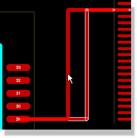
Dragging a horizontal segment moves it vertically while preserving the angle of the adjacent segments.
If you drag inwards on a route corner then the adjacent segments will break into an L45 route, resulting in a 45 degree mitred corner.
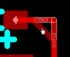
Dragging inwards on a 90 degree corner breaks it into a 45 degree mitred corner.
You cannot drag outwards on a 90 corner (unless you turn off Trace Angle Lock). If you want to move a segment then you should drag the segment as above.
If you drag a 45 degree corner you can again do so inwards and it will create two new segments while maintaining L45 routing.
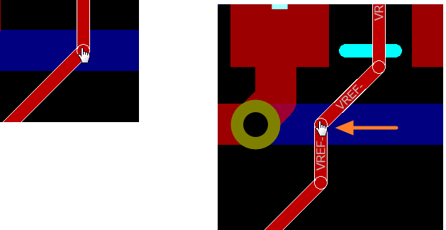
Dragging inwards on a 45 degree corner creates two new segments while maintaining L45 routing.
If you drag in the middle of diagonal segments with trace angle lock off then the diagonal segment will move such that the angle between the tracks at both ends of the segment is preserved.
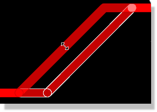
Dragging a diagonal segment with trace angle lock off preserves the angle at both ends of the segment.
If you drag in the middle of diagonal segments with trace angle lock on then the behaviour depends on the angle of the diagonal. If the angle is a multiple of 45 degrees then dragging will be as when trace angle lock is off (see above). However if the angle is not a multiple of 45 degrees then a new corner will be created. This is designed so that, in the common case of adjusting a mitre, the angle between the diagonals is preserved.
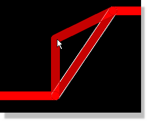
Dragging a diagonal segment that is not a multiple of 45 degrees creates a new corner.
This last situation puts you entirely in manual mode. Once the route is no longer L45 all edits will be 'pulling points' instead of dragging segments. To be avoided unless necessary.
As you edit routes you can see the length of the route as well as the net and the current status of DRC Awareness on the status bar.
While these rules may seem a little obscure in textual format you should quickly find them both easy and intuitive to use.
To re-route a section of tracking
- Tag the route as described under Tagging a Route .
- Place a new section of tracking starting and finishing on the tagged route. Proteus will then remove the section of tracking that the new route shorts out.
Note that vias which are made redundant (i.e. secondary vias) will also be removed, along with the shorted out section.
Modifying a Curved Route
Modifying a curved route with Push editing is the same as modifying an L45 route as described above. Namely, if Design Rule Aware editing is turned on, then push editing can be toggled via SHIFT+P. If design rule aware editing is turned off then push editing is off because there are no longer any obstacles on the board to be pushed. These options can also all be controlled from the Route Command Centre
Curved corners can be dragged towards 90 degrees.
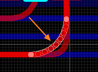
Dragging a curved corner outwards towards 90 degrees.
By default the minimum curve radius is an automatic value, but you can override it manually on the Mitre Parameters dialogue form from the Edit menu, using the Minimum Distance field in the Distance group.
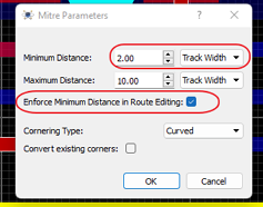
Overriding the automatic minimum distance on the Mitre Parameters dialogue form.
You can also drag curved corners inwards, enlarging the radius of the curve until one of the adjacent segments hit the minimum length.
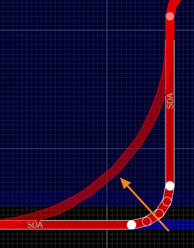
Dragging a curved corner inwards enlarges the radius until an adjacent segment reaches its minimum length.
Straight segments between curves can also be dragged. In the 'C' topology the curve can be dragged inwards (radii getting smaller) until we hit the minimum as discussed above or outwards (as shown below) until we form a semi-circle.
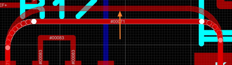
Dragging the straight segment of a C topology outwards until the curves form a semi-circle.
An 'S' topology is slightly more complex. In this case, the segment length is maintained and the segment position is moved with the cursor. The curves either side increase and decrease radius in equal magnitude in order to facilitate the translation of the 'moving segment'.
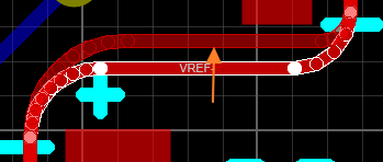
Dragging the straight segment of an S topology translates it, with the curves either side changing radius equally.
Note that you cannot edit the curves (serpentines) applied to differential pairs or length matched routes in this way. Dragging a length matched serpentine instead will allow you to position the serpentine in a different part (end) of the route.
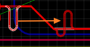
Dragging a length matched serpentine repositions it along the route rather than editing its curves.
Use SHIFT+C to toggle curves on and off while routing. You can also convert L45 mitres to curves globally via the Mitre All Tracks on Layout command on the Edit menu, or locally to a single route via the Mitring sub-menu on the right click context menu.
Design Rule Aware Route Editing vs Guided Route Editing
By default route editing is design rule aware and so all of the techniques above require enough room on the board to complete. The other mode of operation is known as guided route editing with SHIFT+A toggling between modes and the current mode being shown on the status bar.
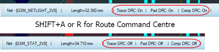
The status bar showing whether design rule aware editing or guided editing is in force.
When you are in design rule aware editing mode you can't drag a route into violation and everything is safe. However, there are times when there is no legal solution to a route edit. If for example a pad trace violation occurs at the pin connection there is likely no route edit that will be design rule compliant. What you'll see in this situation is a run-once error box and a status message prompting you to toggle DRC awareness off for the current route editing operation.
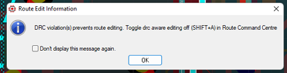
You can't make a DRC aware route edit when the route is already in violation.
When you are working with drc aware editing switched off (in guided mode) it's a really good idea to make sure Visual DRC is turned on because this will help the edit in two ways:
- The border of the viewport will change colour if a violation occurs anywhere on the route. This is especially helpful for large routes or at high zoom where the problem may be off screen.
- If you move into violation with an object inside the viewport that object will change colour to show the violation. This makes it easier to make fine adjustments.
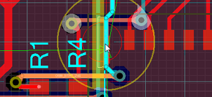
Violations in the viewport are highlighted to allow dynamic editing.
If Design Rule Aware route editing is off then by definition Push editing is disabled since there are no objects contributing obstacles to be pushed.
Default ON or Default OFF ?
We have set Design Rule Aware editing defaulted on because it's a safer option and you can only push edit when the system knows about design rules and clearances. However, it is situation dependent and also a matter of preference. There may well be a lot of violations caused by a component move for example and DRC awareness needs to be toggled off for all of the resultant tidying. Also, some engineers prefer to sort localised design rules (design rule rooms around large IC's) at the end of the routing phase and so work with a lot of violations as a matter of course. In this situation you're best just leaving DRC awareness off altogether and then turning it on for space saving drags or final tidying.
Both modes are useful so the best option of all is to learn the toggle shortcut and then switch between modes according to the situation.
Auto-Completing a Route
When routing tracks on the PCB Proteus searches ahead of the mouse and displays a shadow track to a legal destination. You can then simply hit the ENTER button on the keyboard to automatically complete the route as shown by the shadow track. The shadow track will update as you route with the mouse. This allows you to guide the process and then auto-complete when you are happy with the result.
Auto-complete is on by default but can be turned off via Route Command Centre or SHIFT+S. For performance reasons Auto-Complete will not be available for a route if the destination is on another layer or if tracks have been pushed.
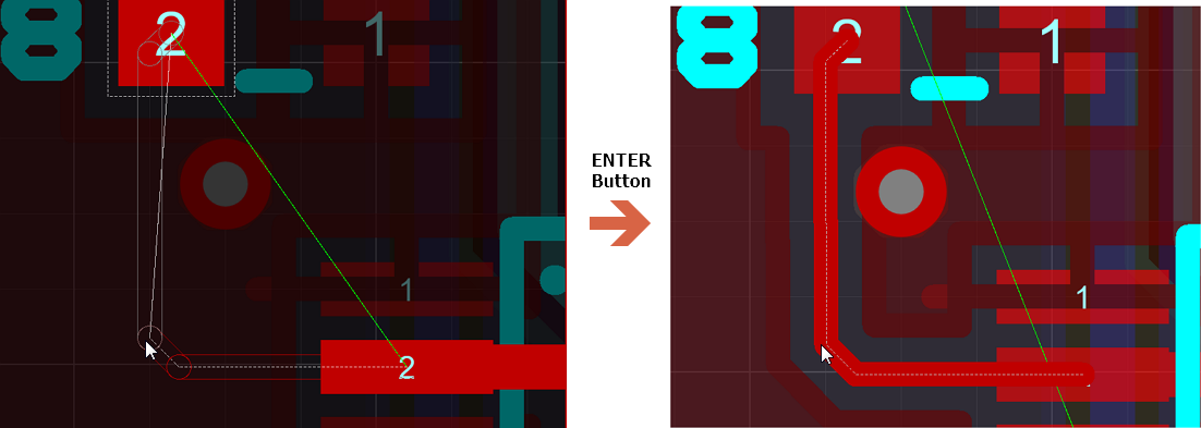
The shadow track showing the route that ENTER would complete.
Length Matching Routes
Length tuning or length matching is often used with higher speed or longer distance signal runs on the PCB to improve signal timing or signal integrity. The basic idea is that the shorter trace follows a detour or meander in order to lengthen it to match the length of the longer trace. Length matching can be configured from the Configure Length Matching command on the Technology menu and tracks can then be length matched by selecting the routes and then choosing the appropriate match command from the right click context menu.
See Also:
Teardrops (on Pads)
Placing teardrops at the connection point between track and pad is often useful in preventing drill breakout during board manufacture. Proteus includes both a global configuration for teardrops and a local override on a particular pad/connection.
Global Configuration
The teardrop configuration dialogue is launched from the Technology Menu as shown below.
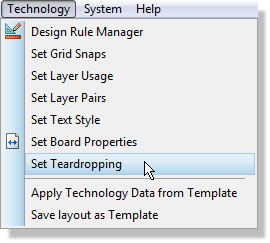
Launching the teardrop configuration dialogue from the Technology menu.
In the Teardrops group, the Enable checkbox switches teardropping on globally. Include undrilled pads extends it to pads with no drill hole. Where teardrops are used they would normally be applied to drilled pads only; the option for undrilled pads is included for completeness.
The Max annular ring setting gates the creation of the teardrop on the copper thickness between the edge of the hole and the edge of the pad. You can therefore specify a maximum annular ring size below which a teardrop connection will be made. In undrilled pads the distance considered here is centre pad to furthest pad edge.
The Teardrop length setting controls the depth from the pad onto the track with which to form the teardrop. It is expressed as a multiple of the track width (x Width) in order to ensure a consistent gradient and shape across various pad sizes on the PCB.
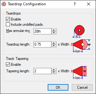
Teardrop Configuration Dialogue Form.
This length should be considered as a maximum teardrop length. If the length that the teardrop extends onto the track is longer than the section of track (because of a corner), the teardrop will be shortened such that it fits onto the connecting section of track.
If the generation of a teardrop connection would violate a design rule then it will not be generated at all.
Teardrops are dynamic. After placement you can edit the track entry point to the pad and the teardrop will re-generate automatically. Once enabled teardrops will automatically be created on route completion or edit.
There is a modest performance overhead to turning teardrops on early in the design process but on an average sized board it shouldn't make too much of a difference with a modern PCB.
Local Override
The edit single pin dialogue allows you to control the teardrop connection to a single pad. The default is the global configuration settings as described above but you can either force enable or force disable if necessary.
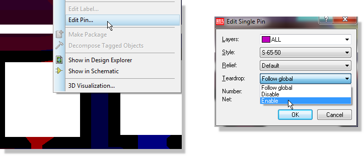
Forcing a teardrop connection on or off for a single pad in the edit single pin dialogue.
Note that teardrops are fully design rule aware and will not be added in cases where their presence would violate an existing design rule.
Teardrops are fully DRC aware and therefore are dependent on the netlist. Clearing down the netlist will remove all teardrops on the board.
Troubleshooting
When teardrops don't appear where you would expect it is normally for one of three reasons:
- Incompatible annular ring.
- Incompatible teardrop length.
- Design rule errors.
Annular Ring
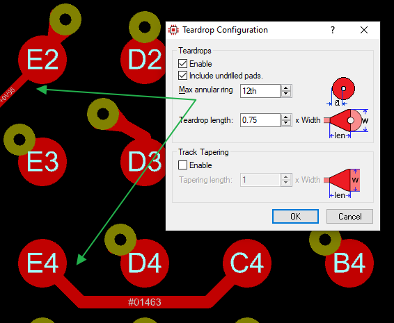
No teardrops on the BGA balls because the ball radius exceeds the maximum annular ring value.
In this example the teardrops are not present because the radius of the BGA ball is larger than the maximum annular ring value. Where a pad is undrilled the distance measured for annular ring is from centre pad to edge where track connects. The solution is to increase the size of the annular ring: setting it to 13 thou in this example would cause the teardrops to render.
Teardrop length
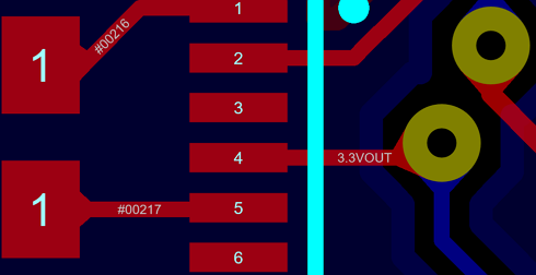
No teardrops on the long finger pads because the pad copper would hide them.
In this example there is no teardrop into the long finger pads of the IC. Since the connection is made to the short side of the rectangle (width) the distance measured for 'annular ring' is from centre pad to that side which is normally greater than the specified teardrop length. In summary, the teardrop would be hidden by the copper of the pad. If you really want teardrops here you would need to increase the teardrop distance value to more than half the length of the pad. However, this would likely result in some odd looking teardrops elsewhere.
Design Rules
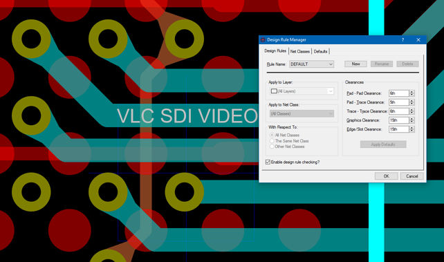
A teardrop missing from one via because rendering it would violate the trace to trace clearance.
In this example, there is a teardrop missing from one of the vias. The distance between the top of the via and the track above is 5 thou. The pad to pad clearance is specified as 5 thou and so this is fine. However, the teardrop would render from the top of the pad and the trace to trace clearance is specified as 6 thou. The teardrop cannot therefore render as it would violate the design rules to do so. The solution is normally to adjust spacing on the layout accordingly.
Teardrops (on Tracks)
Teardrops on tracks, commonly known as track tapers, are small shapes designed to gently adjust the width of the track from the normal routing size down to the necked routing width. The goal is to avoid the sudden change in width seen with a severe change in track size. The tapered trace adds an angled piece of copper to taper the track thickness improving the mechanical structure of the change in thickness. Trace thickness changes can be there for mechanical reasons (like routing from a flexi area to a rigid area) or for signal integrity reasons where a high speed line needs thinner tracking to connect to a terminating pin/ball. It can also be helpful in impedance control with RF routing.
A track taper easing the transition between a full width track and a necked track.
Functionally, the teardrop between the thick and thin tracks behave identically to those between a pad and a track. Track tapers are enabled from the Track Tapering group on the same teardrop configuration dialogue form (Technology menu), which has its own Enable checkbox and a Tapering length expressed as a multiple of the track width to ensure consistency across the board. Track tapers are also dynamic and will re-generate after route edit operations.
See Also:
Mitring a Route
Proteus will allow you to mitre the tracks on the board either as a global command on all the tracks on the board (Mitre All Tracks on Layout, on the Edit menu) or on a per track basis (the Mitring sub-menu on the track context menu). This is typically at its most useful as a post routing step to minimise track length or to avoid solder traps.
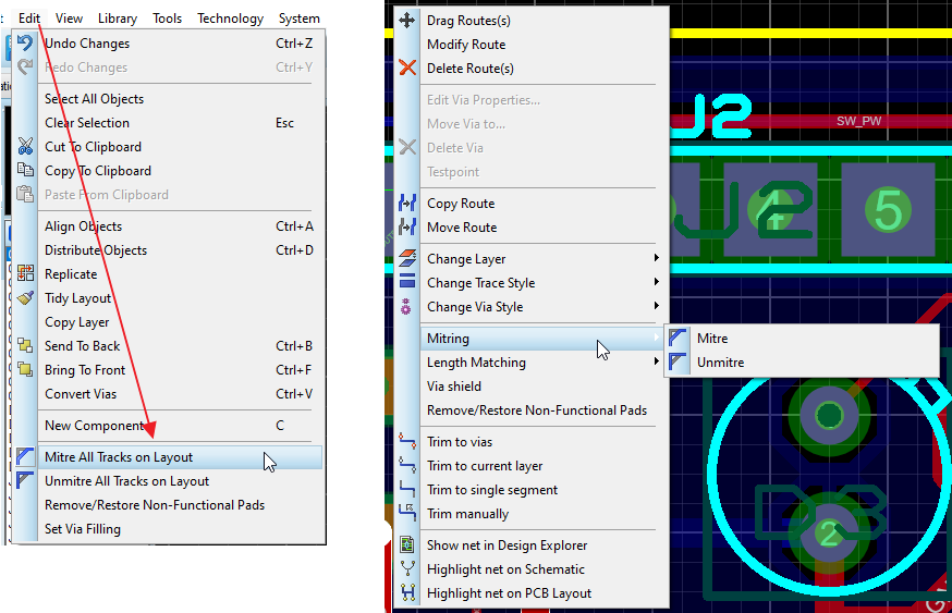
Mitre traces from the Edit menu (Left) or by route context menu (Right)
The resulting Mitre Parameters dialogue depends on which of these options you select. The most common and useful would be to transform a single route, or a selection of routes, locally via the context menu. To do this either:
- Right click on a single route and invoke the Mitre command from the resulting context menu.
OR
- Hold CTRL down and left click to tag multiple routes.
- Right click on one of them and invoke the Mitre command
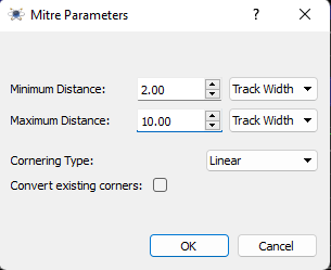
Local Mitring Dialogue Form
The Distance group allows you to change the Minimum Distance and Maximum Distance for the mitre, expressed in track widths, mm or thou. The Cornering group lets you set the Cornering Type between Linear and Curved and, importantly, tick Convert existing corners. That checkbox together with the cornering type is what enables you to edit and change existing routes. If the checkbox was not selected only 90 degree corners would be mitred.
Things are largely the same if you choose to effect a global mitre change via the Edit menu command.
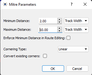
Global Mitring Dialogue Form
The only difference here is the Enforce Minimum Distance in Route Editing checkbox. This is discussed in the curved route editing section above, although it applies also to normal segment dragging.
Important Note:
One common item of confusion is what a mitre actually is. A mitre is a corner cut out of two 90 degree routes. It sounds obvious but it's easy to be confused why a mitring command has no effect. For example, the following is not a mitre and so any mitring commands will not impact this route at all.
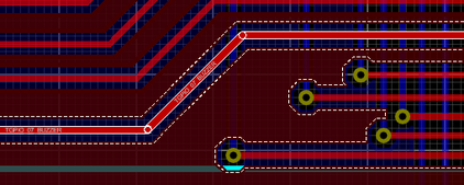
A 45 degree corner that is not a mitre, so mitring commands have no effect on it.
Note that running the unmitre command after a mitre does not guarantee that the board will be returned to the condition it was in prior to mitring. For example, you may have manually mitred tracks on the board which will be unmitred by a global unmitre. If you want to undo a mitre operation directly you should use the undo command (CTRL+Z on the keyboard by default).
Glossing a Route
Glossing is an automatic tidying pass for routed tracks. Its main job is to remove the small artefacts of manual routing: tiny segments and wobbles left by mouse movement (typically near the pads), corners that are almost but not quite 45 degrees, and detours that are longer than they need to be. It can also square up the entry into a pad and apply a minimum mitre to right angle corners. The result is copper that is shorter, cleaner and easier to review, without changing what is connected to what.
Two commands are provided on the route context menu:
- Gloss..., which opens the Gloss Route dialogue form so that you can tune the effort and options and preview the result before applying it.
- Auto-Gloss, which applies a full strength gloss immediately using the default options, pulling detours fully tight and squaring up pad entry.
To gloss a single route, right click on it and select Gloss... or Auto-Gloss from the context menu. To gloss several routes together, hold CTRL down and left click to tag the routes, then right click on one of them and invoke the command. Glossing more than one route at a time is particularly useful after a block edit or a component nudge, where several tracks have been left with small kinks in the same area.
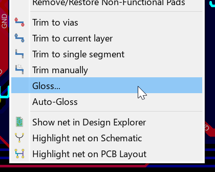
The Gloss and Auto-Gloss commands on the route context menu.
A gloss pass will, depending on the options chosen:
- Absorb sliver segments, meaning segments shorter than a configurable fraction of the track width, which removes routing trembles.
- Straighten corners that are close to 45 degrees onto the exact angle.
- Pull detours tight to reduce the route length, within a displacement budget set by the effort level.
- Square the entry into pads, so that the final approach meets the pad orthogonally with a short straight stub of at least one track width. Entries are aligned to the 45 degree routing compass; the rotation of the pad itself is not considered.
- Chamfer right angle corners to a minimum mitre length, where that option is enabled.

A route before and after glossing, showing sliver removal near the pad and a squared pad entry.
Glossing is safe by construction. It runs only on routes that are already clear of design rule violations, it verifies both the design rules and the connectivity of the result before accepting it, and it reverts any route where the check fails. Arcs and serpentines on a route are treated as landmarks and preserved. The whole operation is a single undo step, and glossed routes are left tagged so you can inspect what changed.
Some routes are deliberately skipped, with a message on the status bar. Differential pairs are not glossed; re-route the pair together instead. Length matched routes are not glossed, because shortening them would break the match. A route that is not clear of design rule violations is skipped; repair or re-route it first.
Gloss changes route geometry only. It never changes which pads a route connects. If you want to convert corner styles across the whole board rather than tidy the selected routes, see Mitring a Route above.
See Also:
Copying a Route
To duplicate a route
- Tag the route as described under Tagging a Route .
- Click right on the tracking to display the context menu.
-
Select the Copy command.
-
Click left at each position for the duplicate routes; click right to finish.
This feature provides an excellent way do memory buses and other repeated patterns of tracking
Deleting a Route
To delete a route
- Tag the route as described under Tagging a Route .
- Click right to display the context menu.
- Select the Delete command.
Any interconnections specified in the netlist that were formed by the deleted tracking will automatically appear as ratsnest lines.
Note that you can also delete all tagged tracking by using the Block Delete icon. This can be quicker than the above procedure if no other tracking is tagged.
To delete a section of a route
- Right depress the mouse at the start of the section of route you want to delete.
- Drag the mouse to the end of the section of track you want to delete and release the right mouse button.
- The section will now be highlighted. Proceed as outlined above to delete.
See Also:
Tidying the Routes
Extensive route editing can lead to the creation of unwanted secondary nodes between tracks segments that join at 180 degrees. These nodes waste memory and also degrade the quality of plotted output. One of the processes carried out by the Tidy command is to scan for and remove such nodes.
The Tidy Layout command may be found on the Edit menu.
The Tidy command removes redundant nodes only. For a fuller cleanup of selected routes, including sliver removal, corner smoothing and squared pad entry, see Glossing a Route above.
Route Placement - No Netlist
We do not recommend professional board layout without the benefit of a schematic and a netlist as it renders Proteus blind to connectivity and severely limits functionality such as power planes.
Placing a new trace on the primary layer is done by first selecting the Trace icon and the required trace style from the Object Selector and then left click to start placing a trace. Placement will follow the path of the mouse while obeying the default board constraints as defined in Design Rule Manager. Left clicking at consecutive nodes (change of direction) will commit the route placement to that point and right click will finish track placement.
Double clicking the mouse will place a via if it is legal to do so and routing can then continue on the associated layer as defined by the Layer Pairs command. Pressing SPACE will also place a via and switch layers. If you want to continue on a layer other than the paired one, use PGUP and PGDN to cycle the valid layer destinations before you place the via.
The type of via used will be defined by the drill passes and layer stackup for the project. The drill range of the via will be the shortest available, given the specified drilling passes. You can also place, replace, tag, drag and delete vias manually in this mode. The mouse buttons work in the same was as for ordinary objects.
You can change layers whilst routing using the Layer Selector keyboard controls. The default controls for these commands are PGUP (Next Layer Up), PGDN (Next Layer Down), CTRL+PGUP (Top Layer) and CTRL+PGDN (Bottom Layer); you can configure your own shortcuts via the Set Keyboard Mapping dialogue on the System menu.
Should you start to enter a trace, and then decide you wish to abort it entirely, simply press the ESC key.
Troubleshooting Route Placement
Performance Problems in Push Mode
This normally happens because a lot of objects are being pushed. Bear in mind that a via push can in turn push multiple tracks on different layers, some of which in turn might push other tracks as well. In order that you can move backwards and unwind all of the pushes at the same time these push calculations need to happen every time the mouse is moved until you commit the changes (even if you are past the objects you've moved). So, if you simply keep routing without anchors things will slow down. The best way to use push mode is:
- Push object(s) until you're happy with their current position and can proceed past them in the way you want.
- Left Click to place an anchor. This commits everything to date, including all the objects, so no more push operations are needed.
- Repeat as needed.
Cancelling the route and pressing undo (CTRL+Z) can return everything to the way it was before route placement started if you change your mind.
This probably isn't necessary when few objects are being pushed and there's space but definitely will be on complex multi-layer boards with lots of tight, parallel tracking.
Can't Push Objects / No Entry Sign
This basically means that the push has hit an obstacle. Most often it's obvious why (sometimes by zooming out if the problem is outside the current viewing area). However, there are a couple of possible reasons why you can't push an object that you think you should be able to.
- If it's a via it's quite likely to be blocked on another layer.
- If it's a track it might well be length matched or a diff pair. These are treated as immovable. If it's on net <None> it also can't be moved (so that you can connect to it if necessary).
Visual DRC will give you an indication of what might be immovable since objects that can be pushed are not enlarged by their clearances. Note that this means the object might be able to be pushed; it still won't be pushable if it's blocked on the board.