CREATING TEMPLATES
Overview
Most users will want to create one or more Templates of their own to reflect the type of boards that they develop. This is an extremely straightforward process:
- Define Technology Data.
- Define Physical Board Skeleton.
- Save the Template.
Defining Technology Data
The technology data block stored in a Template file covers the settings on the Technology menu and a little more besides. Each of the sections below names the command that opens the relevant dialogue.
Design Rules
Opened with the Design Rule Manager command, this dialogue allows you to define and organise board constraints and also to provide routing information for the auto-router. Note that on the Net Classes Tab you can create a new net class. This allows you to set up 'placeholders' so that if you work on a schematic and define that net class the design rules will be picked up when you initialise the layout file from the template.
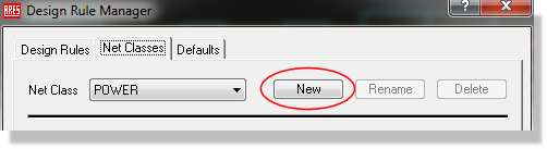
Creating a new net class from the Net Classes tab of the Design Rule Manager
See Also:
Design Rules and Net Classes (Tutorial)
Grids
Opened with the Set Grid Snaps command, the Grid Configuration dialogue allows you to specify the snap settings for both imperial and metric co-ordinate systems. It also allows you to specify the default units of measurement for a new session.
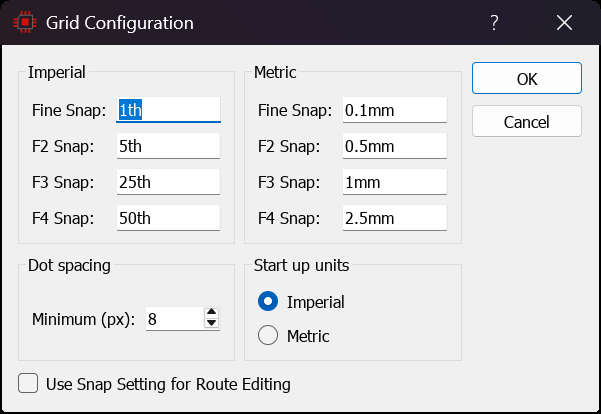
The Grid Configuration dialogue, showing the imperial and metric snap settings
The start-up units define which units Proteus defaults to when you start a new session rather than which units you were last working on when you closed Proteus.
Layer Stackup & Drill Spans
Opened with the Set Layer Stackup command, the Edit Layer Stackup and Drill Spans dialogue provides information on how many copper layers are in use and, together with cores and pre-preg, the construction of the PCB. This information is then exported in the CADCAM readme file for the fab house and also used by Proteus to verify via drill ranges and form connections to plane layers.
The stack distinguishes mechanically drilled spans from laser-drilled micro-via spans, applying the appropriate aspect ratio and minimum hole size constraints to each, and the Stackup Wizard can build a 1+n+1 HDI construction for you. The Layer Stackup topic covers this in full.
The board thickness used by the 3D Viewer and by the IDF output is derived from the stack construction. It is a consequence of the layers, cores and pre-preg you specify here rather than a setting in its own right, so it changes whenever the stackup changes.
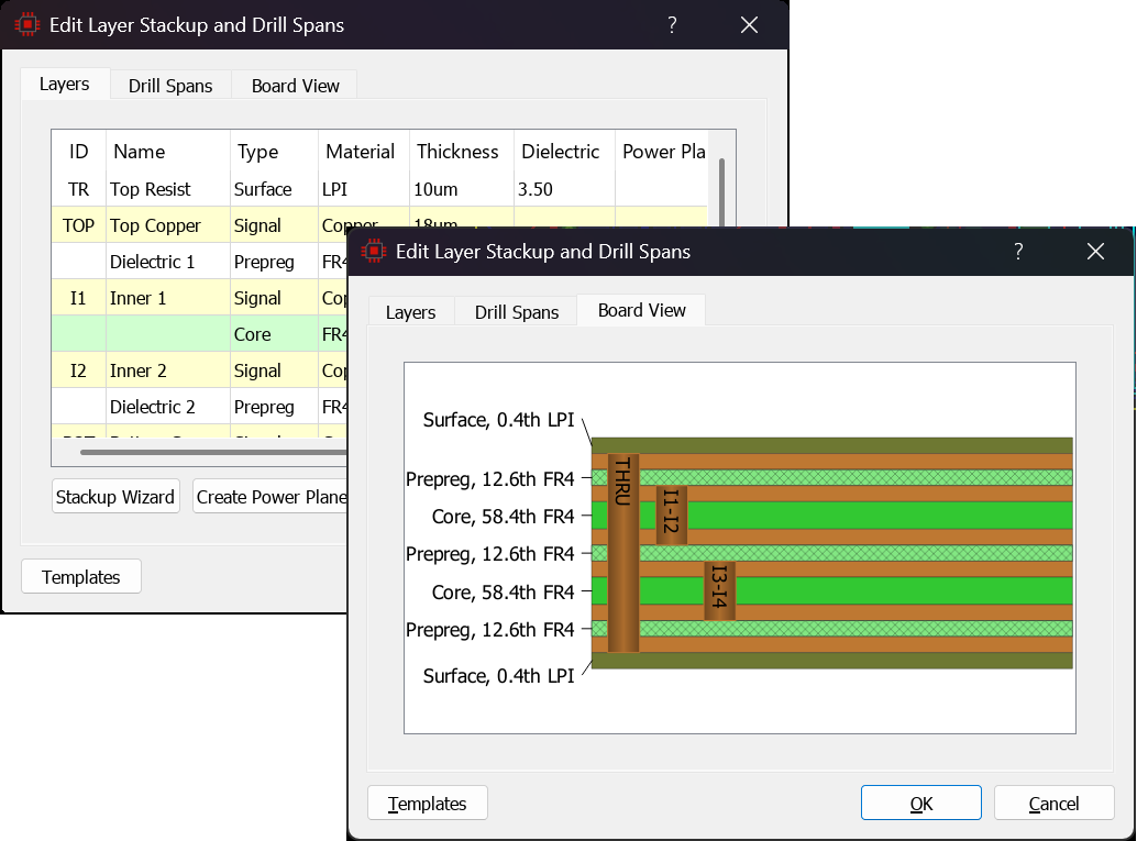
The Edit Layer Stackup and Drill Spans dialogue, showing the board construction and its drill spans
See Also:
Layer Pairs
Opened with the Set Layer Pairs command, the Edit Layer Pairs dialogue allows you to specify the via through level for each layer on the board. This is used when routing manually and determines which layer you end up on when you place a via.
For example, on a two layer board, placing a via on top copper will take you to bottom copper and placing a via on bottom copper will take you to top copper.
The settings on this dialogue form are governed by the layer stackup. For example, if you have a defined a 4-layer board (Top Copper, Inner 1, Inner 2, Bottom Copper) you will not be able to set a layer pair either from or to inner 9 on this dialogue form.
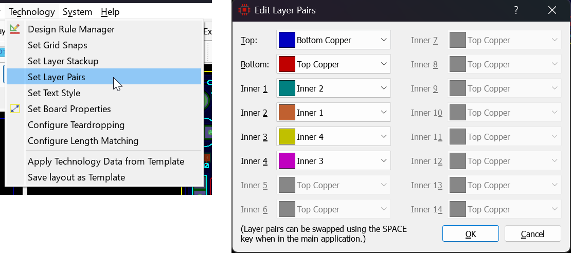
The Edit Layer Pairs dialogue for a six layer board
Using the SPACE bar in the main application will toggle the current layer according to the layer pair configuration for that layer.
See Also:
Layer Pairs and Manual Routing (Tutorial)
Length Matching
Length tuning or length matching is often used with higher speed or longer distance signal runs on the PCB to improve signal timing or signal integrity. The basic idea is that the shorter trace follows a detour or meander in order to lengthen it to match the length of the longer trace. Opened with the Configure Length Matching command, the Length Matching dialogue enables various configurations of serpentine pattern which will then be used when you length match traces on the board. It is tabbed, with a separate set of parameters for normal length matching, for differential pair length matching and for differential pair phase matching, and all three sets are stored in the template.
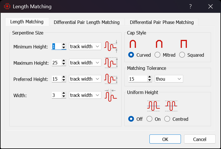
The Length Matching dialogue, configuring the serpentine pattern used when tuning traces
See Also:
Length Tuning is part of the Advanced Features Set and is available from PCB Design Level 2 onwards.
Teardrop Configuration
Placing teardrops at the connection point between track and pad is often useful in preventing drill breakout during board manufacture. Opened with the Configure Teardropping command, the settings in this dialogue control the placement of teardrops on the layout.
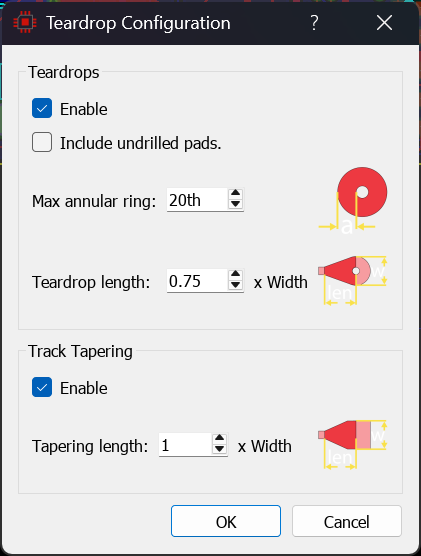
Teardrop Configuration
See Also :
Text and Graphics
Opened with the Set Text Style command, the Default Text Style dialogue allows you to configure font settings and visibility for part reference, part values and 2D Graphics. You can also define the width of any 2D graphic lines used on the board.
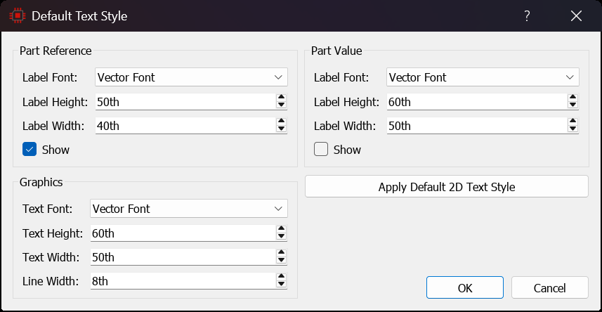
The Default Text Style dialogue, setting the fonts used for part references, values and 2D graphics
Board Properties
Opened with the Set Board Properties command, this dialogue configures the global work area. Maximum Width and Maximum Height set the extent of that area, which is the space the layout is drawn in rather than the size of the finished board. The Board Name field names the board, which matters when a project carries more than one.
Board thickness is not set here. As described under Layer Stackup & Drill Spans above, it follows from the stack construction.
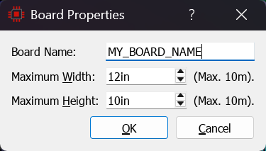
The Board Properties dialogue, setting the board name and the extent of the work area
Defining Board Skeleton
The board skeleton can consist of board edge, 2D Graphics and mounting holes. In the example below we have set up a simple rectangular board edge with 3mm mounting holes positioned for mini-locking PCB supports and have included the Labcenter company logo.
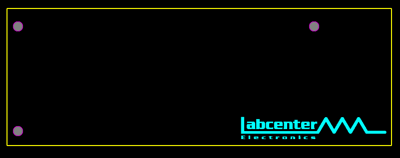
A board skeleton: a rectangular board edge with mounting holes and a company logo
You can also include components and other objects in a template. In the example below we have a Eurocard with a placed connector. Note that tracking is not stored in a template, so the connector arrives placed but unrouted.
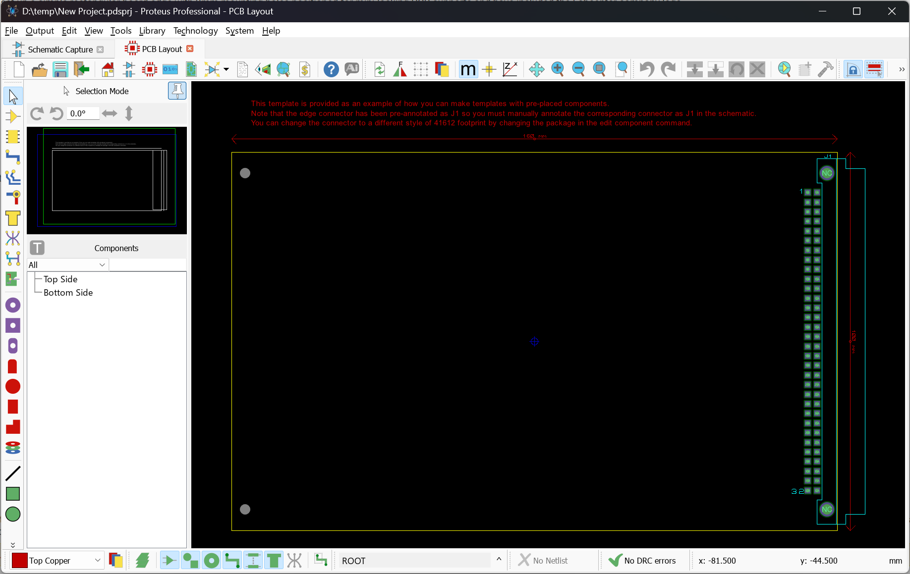
A Eurocard template with a connector already placed
See Also:
Mounting Holes and Pad Styles (Tutorial)
It is crucial to understand that templates that contain components will need to have their annotations matched to the schematic. In other words you need to make sure that the connector (J1) corresponds to the J1 connector on your schematic. If it corresponds to the J2 connector on the schematic then you need to change the annotation on the layout to be J2 before you netlist. Clearly, if you save a template with many components this may involve considerable manual re-annotation on the layout.
If you are at all unsure about this we strongly recommend that you do not save templates with components. You can easily strip them from an existing layout with the selection filter.
Saving the Template
Having completed the Template configuration we simply use the Save layout as Template command on the Technology Menu and provide a sensible name.
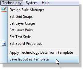
Saving the layout as a template
Whenever we start a new layout we will now be offered this Template as an option for the new board.
More information on Saving Templates can be found here.