GENERAL EDITING FACILITIES
Object Placement
Proteus supports many types of object, and full details of the purpose and behaviour of each type is given in the chapter on Object Specifics. However, the basic steps for placing an object are the same for all types.
To place an object:
- Select the appropriate icon from the Mode Selector toolbar for the category of object that you want to place.
- If the object type is Component, Terminal, Pin, Graph, Symbol or Marker, select the name of the object that you want from the selector. For Components, Terminals, Pins and Symbols, this may first involve picking it from the libraries.
- If the object is orientable, it will have appeared in the Overview Window. You should now adjust its orientation to that which you require by clicking on the Rotation and Mirror icons.
- Finally, point on the Editing Window, click left to enter placement mode, move the mouse to the location on the schematic where you want to place the object and left click the mouse to deposit the object and exit placement mode. The exact procedures vary for each object type but you will find it all fairly intuitive and similar to other graphics software.
See Also:
Selecting Parts from the Library (Tutorial)
Placing Objects on the Schematic (Tutorial)
Tagging an Object
Tagging or highlighting an object can be done in several ways as detailed below :
- Entering selection mode and left clicking on the object.
- Right clicking on the object (this tags the object and presents you with that object's context menu).
- Dragging a box around the object (or objects!) using the left mouse button.
- Modeless selection by clicking the left mouse button on the object. This is extremely fast and works for all objects except for wires and 2D Graphic objects where one of the above methods must be used.
Normal use would be to use either modeless selection or simply to right click on the object, however it is very much an area for personal preference.
Objects may be de-selected either by right clicking in free space and selecting the Clear Selection option from the context menu or simply by left clicking in free space. The companion command, Select All Objects, is on the same context menu and on the Edit menu.
Two further commands on the Edit menu are worth knowing about at this point. Align Objects, default key CTRL+A, opens a dialogue form for aligning the objects you have tagged. Tidy Design removes unused devices and symbols from the object selectors.
See Also:
Timesaving Techniques & Block Editing (Tutorial).
Object Groups
Object groups allow you to create persistent logical collections of objects that behave as a unit during editing operations. Unlike a tag box selection which is temporary, an object group is saved with the design and remains in effect until you explicitly ungroup the objects.
Why Use Object Groups
The primary purpose of object groups on the schematic is to keep related objects positioned together. If several objects are placed relative to each other (for example, a set of components forming a functional block together with associated labels and graphics) you can group them so that they always move, rotate and mirror as a single unit. This prevents accidental misalignment when rearranging the schematic.
What Can Be Grouped
Most schematic objects can be grouped: components, terminals, device pins, 2D graphics and other graphic objects. Sub-circuits cannot be grouped as they represent a separate level of the design hierarchy.
Wires and buses are connections rather than objects, so they are never members of a group. This does not stop you grouping the circuitry they connect: a wire that crosses the boundary of a group is re-routed when the group is moved, exactly as it would be for an ordinary tag box selection. Bus pins and bus terminals are objects and can be grouped in the normal way.
Creating a Group
To create a group, tag the objects you wish to group using a tag box or by left clicking individual objects, then either select Group Objects from the Edit menu or right click and select Group Objects from the context menu. A confirmation message will appear in the status bar showing the group and its members.
Nested Groups
Groups can be nested to form a hierarchy. If all the objects you select already belong to the same group, the Group Objects command will create a sub-group within that parent group. This allows you to organise complex sections of a schematic into logical tiers.
Selecting and Working with Groups
When you interact with any member of a group, the selection automatically expands to include all members of that group. This applies to both single-object operations (dragging, context menu commands) and block operations on a tag box selection. If the group contains nested sub-groups, these are included as well; the expansion always operates from the root of the group tree.
The following table summarises which operations are group-aware:
| Operation | Group Behaviour |
| Drag | Dragging any group member moves the entire group. Wires crossing the boundary are re-routed as normal. If you click without moving, the group expansion is cancelled and the Edit Properties dialogue opens for the clicked object. |
| Delete | Deleting any group member via the context menu deletes the entire group. |
| Rotate and Mirror | Rotate or mirror commands from the context menu transform the entire group about the clicked object. |
| Block Move | All group members move together. Wires crossing the tag box boundary are re-routed as normal. |
| Block Copy | All group members are copied. The group hierarchy is duplicated with fresh identifiers so the copy is independent of the original. |
| Block Rotate | All group members rotate together about the specified origin. |
| Block Delete | All group members are deleted together. |
| Clipboard and Project Clips | Group structure is preserved through cut, copy, paste and project clip export/import. |
Edit Properties always operates on the individual object regardless of group membership. You can edit a component's properties without affecting the rest of the group.
Ungrouping
To ungroup, tag any member of the group, then either select Ungroup Objects from the Edit menu or right click and select Ungroup Objects from the context menu. This dissolves the entire group hierarchy from the root down, returning all member objects to an ungrouped state.
Groups and the Clipboard
Group structure is preserved when objects are copied via block copy, cut to the clipboard or saved as project clips. When the objects are pasted, the group hierarchy is recreated with fresh internal identifiers so that the pasted group is independent of the original.
Deleting an Object
You can delete any object by pointing at it, clicking right and selecting Delete from the resulting context menu. All wires connected to the object will also be deleted, except in the case of a dot connected to exactly 2 wires, in which case the wires will be joined.
Note that for 2D Graphics objects you must right click on the border of the graphic to invoke the context menu - it is possible that 2D graphics may be placed around or behind another object and it is therefore necessary to ensure that the 2D graphic (as opposed to the other object) is the one you want to action on.
Dragging an Object
You can drag (i.e. re-position) any tagged object by pointing at it (the cursor will change to indicate that the object can be dragged) and then dragging with the left button depressed. This applies not only to whole objects, such as components, but also individually to their labels.
- If the Wire Auto Router is enabled and there are wires connected to it, then these will be re-routed or 'fixed up'. This can take some time if the object has a lot of connected wires; the pointer becomes an hour glass while this is happening.
- If you drag an object by mistake, and all the wiring goes horribly wrong, you can use the Undo command, key CTRL+Z to restore things to their original state.
See Also:
Basic Schematic Entry (Tutorial)
Dragging an Object Label
Many object types have one or more labels attached to them. For example, each component has a reference label and a value label. It is very easy to move these labels in order to improve the appearance of your schematics.
To move a label:
- Tag the object by one of the methods outlined above.
- Point at the label and depress the left mouse button.
- Drag the label to the required position. If you need to position it very finely, you can change the snap resolution using the shortcut keys (by default these are mapped to F4, F3, F2, CTRL+F1) even whilst dragging.
- Release the mouse button to finish.
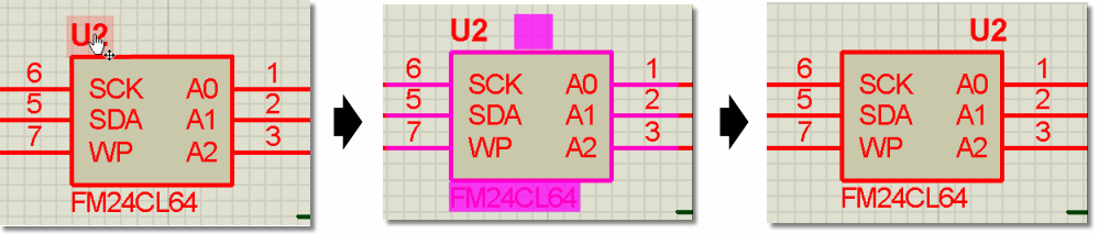
Moving a component label
Resizing an Object
Sub-circuits, graphs, lines, boxes and circles may be resized. When you tag these objects, little white squares called handles will appear and the object can be re-sized by dragging the handles.
To resize an object:
- Tag the object by entering selection mode and left clicking on the object (remember to left click on the border if the object is a 2D Graphic).
- If the object can be resized, a set of little square handles will appear on it.
- Resize the object by pointing at a handle, pressing the left mouse button, and dragging it to a new position. The handles disappear whilst you are dragging so that they do not obscure your view of the object itself.
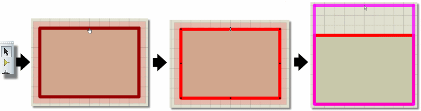
Resizing a 2D graphics object using its handles
See Resizing 2D Graphics for information about advanced use of handles when resizing 2D graphics path objects.
Reorienting an Object
Many of the object types may be oriented, that is rotated through 0, 90, 180 and 270 degrees and reflected in x and/or y. If such an object is tagged, the Rotation and Mirror icons will change colour from blue to red, and will then affect the tagged object.
To reorient an object:
- Tag the object using one of the methods outlined here.
- Click left on the rotation icon to rotate it anti-clockwise, right to rotate it clockwise. The Rotate 180 degrees command turns the object through half a turn in one step.
- Click left on the Mirror icon to toggle its reflection in x, and right to toggle its reflection in y.
It is worth noting that if the Rotation and Mirror icons are red, operating them will affect an object somewhere on the diagram, even if you cannot currently see it. This becomes important if, in fact, you wish to manipulate a new object which you are about to place. If the icons are red, first untag the existing object by pointing at an empty area of the design in the Editing Window and clicking left. The icons will then revert to blue, indicating that it is 'safe' to adjust them.

Rotation Icons
See Also:
Editing an Object
Many of the objects have graphical and/or textual properties that may be edited through a dialogue form, and because this is a very common operation we have provided a variety of ways to achieve it.
To edit a single object using the mouse:
Either:
Right click on the object and select Edit Properties from the resulting context menu.
Or:
Double click the left mouse button on the object.
To edit a succession of objects using the mouse:
- Enter Selection Mode.
- Point at each object in succession and click left.
To edit an object and access special edit modes:
- Point at the object.
- Press the shortcut for Edit Properties (default assignation is CTRL+E). The command is listed under the object context group in the Edit Keyboard Map dialogue form.
For text scripts, this will invoke the external text editor. Also, if the mouse is not over any object, this command will edit the current graph, if any.
To edit a component by name:
- Select Find/Edit Component from the Edit menu, or key its shortcut (default assignation is E).
- Type in the reference name (part ID) of a component.
This will locate and bring up the dialogue form for any component in the design, not just those on the current sheet. After the edit, the screen is re-drawn with the component in the centre. You can thus use this command to locate a component, even if you do not actually want to edit it.
Details pertaining to the operation of the dialogue forms associated with each object type are given in the Object Specifics section of this documentation.
Editing An Object Label
Component, terminal, wire and bus labels can all be edited in much the same way as objects:
To edit a single object label using the mouse:
- Tag the object by pointing at it and clicking left.
- Click left on the label (not the object itself).
To edit a succession of object labels using the mouse:
- Enter Selection Mode.
- Point at each label in succession and click left.
Either way, a dialogue form with Label and Style tabs is displayed. The editing of local text styles is covered under Local Styles.
Copying all Tagged Objects
To copy a section of circuitry:
- Tag the required objects by dragging out a tag-box as described in Tagging an Object.
- Right click within the tagbox and select the Block Copy option from the resulting context menu.
- Move the mouse to lift the copy outline to the required position and click left to place a copy.
- Repeat step 3 as required to place multiple copies.
- Click right to finish.
When components are copied, their references are automatically reset to the un-annotated state so as to ready them for automatic annotation, and prevent the occurrence of multiple instances of the same part IDs.
All block operations (copy, move, rotate and delete) are group-aware. See the table under Object Groups for what each one does to a group.
The Clipboard
Block Copy, described above, works within the current sheet and resets the references of the copied components so that they are ready for annotation. The Cut To Clipboard, Copy To Clipboard and Paste From Clipboard commands work differently: they place the tagged objects on the Windows clipboard, from where you can paste them onto another sheet or into another project. All three are on the Edit menu, on the Edit toolbar and on the context menus.
To move a section of circuitry between projects without using the clipboard, export it as a project clip instead. See Import / Export Project Clip.
Moving all Tagged Objects
To move a set of objects:
- Tag the required objects by dragging out a tag-box as described in Tagging an Object.
- Move the mouse inside the tagbox (the cursor will change to indicate that the block can be moved).
- Depress the left mouse button, drag the outline to the required position and click left to place it.
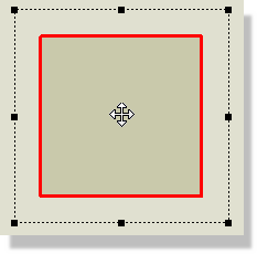
Moving a tagged object
The behaviour of wires during block move is somewhat subtle. Essentially, Proteus will move all wires or parts of wires enclosed in the tag-box without re-routing them, and then, where wires cross the boundaries of the tag-box, it will reroute from the last point inside the tag-box to the first point outside it. It follows that you can control whether a section of wiring is preserved or re-routed according to whether you include it in the tag-box or not.
Deleting all Tagged Objects
To delete a group of objects:
- Tag the required objects by dragging out a tag-box as described in Tagging an Object.
- Right click within the area encompassed by the tagbox and select the Block Delete option from the resulting context menu.
If you delete something by mistake, you can recover it using the Undo command.
Rotating all Tagged Objects
To rotate a group of objects:
- Tag the required objects by dragging out a tag-box as described in Tagging an Object.
- Right click within the area encompassed by the tagbox and select the Block Rotate option from the resulting context menu.
Note that you cannot Block Rotate a tagged section of circuitry if either a sub-circuit or a graph is highlighted (these objects have a fixed orientation). Also, depending on the complexity of the design and in particular whether tagged components are wired up, this operation may take a few seconds to complete. As always, you can undo the rotation via the Undo command.