FIRMWARE DEVELOPMENT
Overview
Writing or editing code in VSM Studio is much the same as in any other IDE. Once you have created or imported your project you can start work in earnest. This section of the documentation details how to perform some common tasks in the IDE.
The EDAi assistants are available from inside VSM Studio and can give you code-level guidance on the firmware you are writing, so consult the EDAi manual alongside this topic.
Adding / Removing / Renaming Files
To add a file to the project
Either
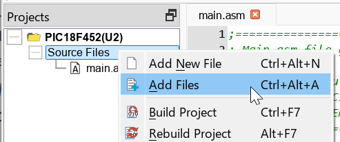
Right click on the project category and select the Add Files or Add New File command from the context menu. Note you must right click on the category (e.g. Source Files) and not on a file itself.
Or
Select the Add Files or Add New File command directly from the Project Menu.
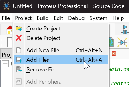
You do not choose which category a file joins. The category is worked out from the file's extension using the descriptor for the project's toolchain, so source files land in Source Files, headers in Header Files and libraries in Library Files, while a file the toolchain does not recognise goes into Other Files. Two categories are filled a different way: Resource Files, which the Add Resource File command on the Project menu populates with the data files your project's peripherals need, and Generator Scripts, which collects EasyHDL scripts by their extension and is described at the end of this topic. Resource Files, Library Files and Generator Scripts always keep their names; any other category can be renamed in the tree.
To remove a file from the project
Either
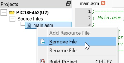
Right click on the file in the project tree and select the remove file command from the resulting context menu.
Or
Select the remove file command on the Project Menu. This will remove the file currently selected in the Project Tree.
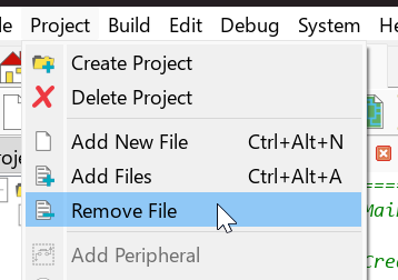
In both cases the file will be removed from the project but will not be deleted from disk.
To rename a file
Right click on the file in the Project Tree and select the rename option from the resulting context menu.
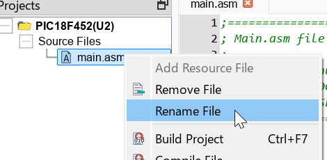
Renaming a file will both rename it in the project and on disk.
Opening and Closing Files for Editing
-
To open a project file in the Editing Window simply double click on the file in the project tree.
-
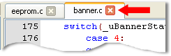
To close a file in the Editing Window use the small cross at the top right of the tab. This will close the file but will not remove it from the project.
-
To switch between open files in the Editing Window use the CTRL+TAB shortcut key or click on the appropriate tab at the top of the editing window.
Find and Replace
To find text in the project
- Launch the Find dialogue form either by right clicking in the Editing Window or from the Edit Menu.
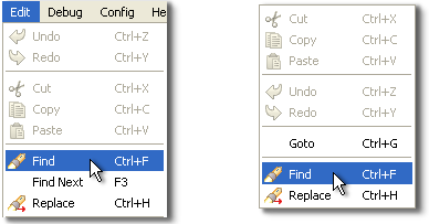
- Enter the string you wish to find and, optionally, the text you wish to replace it with.
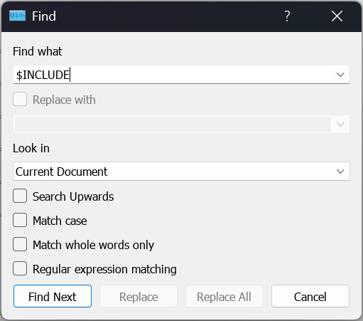
- Specify the scope of the search (current document, all open documents, current project).
- Specify any additional search options. The regular expression syntax is based on the Perl regular expression language but should be considered an advanced option.
You can use the F3 shortcut key instead of the Find Next button when searching through a file for a particular instance of the search term.
Editor Colours and Styles
You can change the look and feel of the IDE by selecting the Editor Configuration command from the System menu. The Fonts and Colours tab of this dialogue form will allow you to change the syntax highlighting options for the various windows in the IDE, while the Text Editor tab provides configuration options for the Editing Window and the Flowchart Editor tab does the same for flowchart projects.
Compiler Settings and Compilation
To compile your project
- Select the configuration you want to build from the combo box at the right hand end of the Build toolbar. Use the Debug configuration when the firmware is to be simulated in Proteus.
- Click on the Build Project button, which is the first button on the Build toolbar, or select Build Project from the Build menu (CTRL+F7). The command is also on the context menu of the project tree.
-
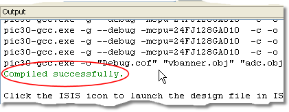
Compiler information will be displayed in the Output window and should end with a 'Compiled successfully' message.
The Build toolbar holds the build commands in the order Build Project, Rebuild Project and Stop Build, followed by Upload, then Project Settings, with the build configuration combo box at the end.
Three related commands sit alongside Build Project on the Build menu:
- Rebuild Project (ALT+F7) compiles every file in the project from scratch rather than only those that have changed. Use it after altering a project setting, since a change of that sort is not tracked by the dependency checking that an ordinary build relies on.
- Clean Project (CTRL+F6) deletes all the output and intermediate files that the compiler has generated, leaving your source files untouched.
- Stop Build (ESCAPE) abandons a build that is in progress.
You can also compile a single file instead of the whole project. Right click on the file in the project tree and select the Compile File command, which is useful for checking that one source file compiles cleanly while the rest of the project is still being written.
To find and fix compiler errors
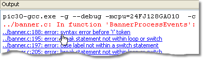
- Locate the error message in the Output Window.
- Click on the message to locate the line in the Editing window.
To find and fix linker errors
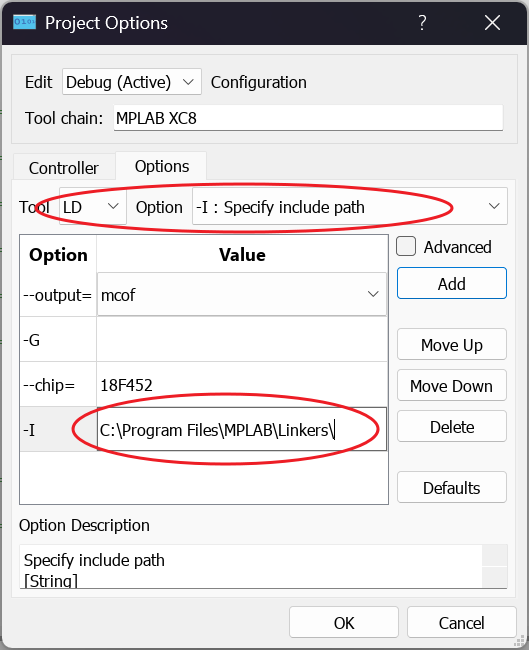
It may be that the error is a linker error or requires that you edit the project settings to bring in a library or include file. To do this, launch the Project Settings command and select the Options tab of the resulting Project Options dialogue.

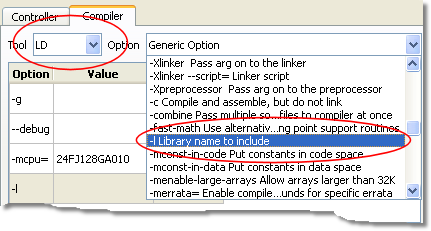
Next, select the tool for which you need to specify additional options (CC is compiler, ASM is assembler, LD is linker etc.) and select the option you need from the right hand side. More information on options will be available in the user manual of the compiler itself, although the most common would be '-L' to add a directory to the library search path.
Add the option and enter the value (directory path for the above example).
Finally, exit the dialogue form and re-compile the project.
Programming a Physical Device
Firmware you have written and simulated can be written straight to a real board without leaving the IDE. The Upload command on the Build menu (CTRL+F8) writes the program to the connected hardware, and the same command has a button on the Build toolbar. You do not need to build first: if the project has not been compiled, or if it was compiled with settings that do not suit the board, VSM Studio compiles it for you before programming begins.
The programmer is chosen per project on the Controller tab of the Project Options dialogue, which you reach with the Project Settings command. Select the processor family and controller first, because the Programmer field then offers only those programmers that can write to the part you have chosen. Selecting a programmer adds an Interface field, and selecting an interface adds whatever settings that connection needs, typically a COM port for a board attached by cable, or a host name, user name and password for a board programmed across a network. Leaving the Programmer field set to None means the project has no upload route.
Several programmers are supplied with Proteus, among them AVRDUDE for AVR and Arduino parts, ST-LINK for STM32 boards, PICAXE for the PICAXE range, an upload tool for MicroPython targets and SSH uploaders for Raspberry Pi and Arduino Yun boards.
Progress and any errors from the programmer appear in the Output window, ending with a 'Firmware upload COMPLETE' message once the board has been written. Your choice of programmer, interface and connection settings is held with the firmware project and stored in the Proteus project file, so you configure the board once and every later upload uses the same settings.
The System Terminal gives you a serial console on the board you have just programmed; it is docked as a tab alongside the Output Window and is described in the Guided Tour.
Working with Proteus VSM
A firmware project does its best work when it is paired with a schematic in the same Proteus project. The compiled output is then picked up automatically by the processor on the schematic, so you can move from writing code to simulating and debugging it without any further setup. Two routes are recommended for arriving at that pairing.
Set up both modules in the New Project Wizard
The simplest route is to ask for the schematic and the firmware together when you create the project. Tick the schematic design option on the wizard's schematic page, then choose Create Firmware Project on its firmware page and specify the family, the controller and the compiler. Proteus creates both modules, places and powers the processor on the schematic and binds the firmware project to it.
Start from the schematic
Where the schematic already exists, or where you would rather draw it first, place the microcontroller on the schematic, right click on it and select Edit Properties. Click the Edit Firmware button on the resulting Edit Component dialogue and VSM Studio creates a firmware project for that processor, with the family and the controller already filled in from the part you placed.
A schematic module can also be added to an existing firmware project by clicking the Schematic Capture button on the module bar at the top of the application frame, but the two routes above are preferred because they bind the processor and the firmware project for you.
Once both modules exist, switch between them using the application tabs at the top of the window, or with the CTRL+TAB shortcut key.
The Breakpoints window lists every breakpoint in the project and lets you enable, disable or clear them from one place; open it with the Breakpoints command on the Edit menu or the SHIFT+F9 shortcut key.
Firmware does not have to be built in VSM Studio at all. A file compiled elsewhere can be attached to the processor by hand through the same Edit Component dialogue, and a large project is often better driven from a third party IDE, as explained in the Introduction.
More information on testing and debugging can be found here.
Generator Scripts (EasyHDL)
As well as firmware source files, a VSM Studio project can host EasyHDL scriptable generator scripts. These live in the Generator Scripts category of the project tree and carry the .ehdl extension. Add, edit and remove them exactly as you would any other source file (see above); they are given EasyHDL syntax highlighting and are excluded from the firmware compile, so they have no effect on the microcontroller program.
When the associated schematic is simulated, VSM Studio contributes each .ehdl file to the netlist as a named generator script. The base name of the file is the script name, so a file named TEST.ehdl provides a script called TEST, and any generator whose SCRIPT property is set to that name will be driven by it. You set this on the schematic by editing the generator, enabling Manual Edits? and adding SCRIPT=basename (the project script does not appear in the generator's Assigned Script list). A single script can therefore drive several generators sharing the same set of test vectors.
The file holds the script body only; you do not write the *SCRIPT ... *ENDSCRIPT wrapper that an on-schematic script object requires.
See the topic on Scriptable Generators in the main simulation help file for the EasyHDL language reference and authoring rules.