MANUAL ROUTING EXAMPLES
Introduction
The examples below cover a range of common routing tasks in Proteus. In all cases it is assumed that the board has been set up with the basics. This means:
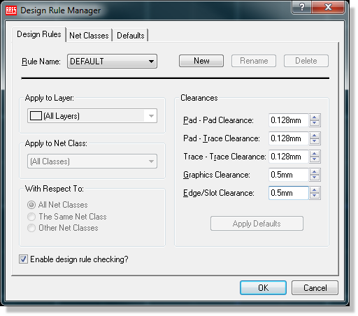
- The basic design rules from the Design Rule Manager and that you have a basic understanding of Net Classes.
- A layer stackup and drill spans have been thought about and defined.
- Layer pairs have been configured as required.
Example: Routing a Simple Connection
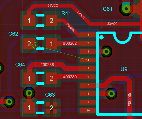
Simple Route required from U9:4 to C62:2
This is a simple example where we can place the route on one layer. The process is:
1) Select Trace Mode icon.
2) Left click on the centre of a pad to start routing.
3) Guide the route towards the destination pad.
4) Press the ENTER key when you're happy with the preview route to accept the automatically created route and complete.

Important Concepts
While trivial in terms of routing, the software is doing a fair bit of work based on information that you (should) have supplied. Understanding how this works will make a big difference when things become more densely packed and complex.
- At the beginning and the end of track placement, Proteus will snap the mouse to the centre of the pad to ensure a solid connection. The amount of snap is based on your settings from the View Menu (but normally toggled by keyboard shortcuts). Typically, you work with a looser snap when zoomed out (e.g. F3 or F4 on the keyboard) and a finer snap when zoomed in tight (e.g. F2). If you are missing the pad centre, change the snap setting to a looser one.
Make sure you understand snap settings and the keyboard shortcuts (from smallest to biggest it's CTRL+F1 -> F2 -> F3 -> F4). You can change the values from Technology Menu - Set Grid Snaps command. The goal is to always work with the biggest snap setting you can ... if you find yourself missing the centre of the pad then chances are good that your snap setting is too fine.
- When you move the mouse to place a track the style (thickness) of the track comes from the Net Class tab of the Design Rule Manager on the Technology menu. Since it is very easy to create your own net classes, this provides the means to automatically route with different but correct trace widths for various power and signal connections.
You can override this behaviour by turning off Auto Trace Style Selection from the Tools Menu (CTRL+T) or by changing the trace style from the Route Command Centre. However, for all but the most simple of boards it is extremely useful and as we'll see in more complex examples, a little time spent setting up net classes will vastly simplify routing the board.
- When you route close to the via or near another pad/track the software will either push it out of the way or stay the required distance away depending on which mode you are in. We'll look at these options below but they are controlled either by keyboard accelerators (SHIFT+P to toggle push mode) or from the Route Command Centre. These distances are set up in the Design Rule Manager on the Technology menu.
Three more in-route toggles are worth learning alongside SHIFT+P: SHIFT+V turns via pushing on and off, SHIFT+D turns the Visual DRC aura on and off, and SHIFT+N switches between the track style and the neck style. All of them can also be set from the Route Command Centre, and all of them, like every other command, can be remapped from the keyboard configuration dialogue.
The single most important thing you can do to make manual routing easy is to set up both your Design Rules (clearances) and your Net Classes before you begin. The more complicated the board, the more important this becomes but even on simple boards it's a vital QA tool as well as a productivity win.
Example: Guiding a Route with Anchors
This is the single most important skill to master, whether completing a single route or weaving a complex push route through a densely packed BGA.
Simple Route required from U9:4 to C62:2
This is the same route as before except instead of using the auto-complete we are going to place anchors to guide the route exactly where we want it to go. The basic technique is to left click to commit the route up to the point of the mouse. You have two degrees of freedom (two track segments) to allow a more natural flow with route guidance. You'll find that normally therefore you left click to commit some track before you change direction. Here is a full sequence for this route:
1) Select Trace Mode icon.
2) Left click on the centre of a pad to start routing.
3) Come straight out and then up from the pad (remember two degrees of freedom). Left click to commit.
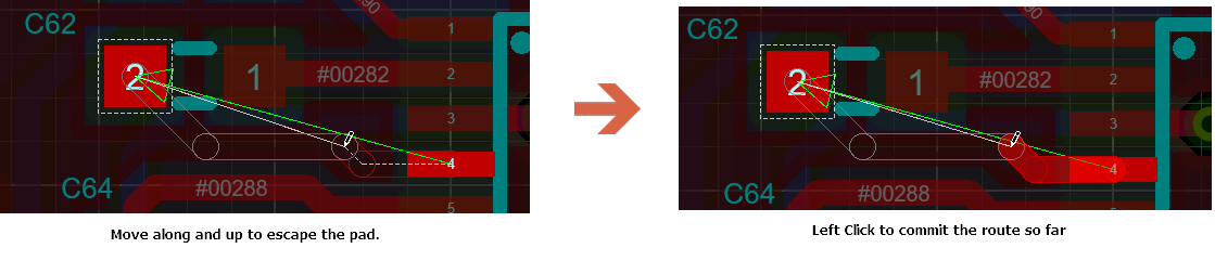
4) Head along the horizontal until nearly at the destination and then head up for a little 45 corner. Left click to commit.
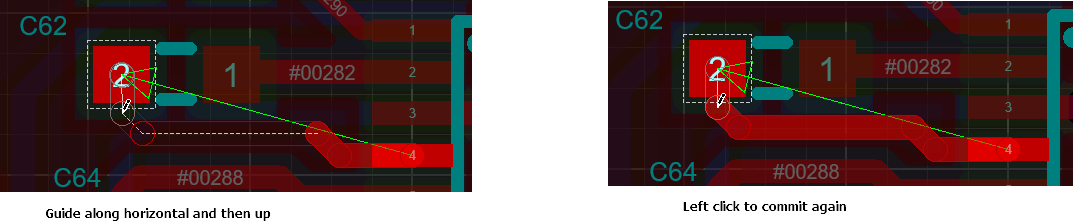
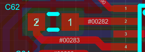
5) Move mouse into destination pad and left click to complete the connection.
Important Concepts
This was probably harder to explain than to actually do but the technique is very important later on when it comes to pushing other objects out of the way and it will probably also lead to the neatest tracks once you become proficient in it's use. Here are a few things to remember.
1) You can unwind the track so far and go backwards if you need to! Simply move the mouse back over the route segments you've completed to erase them and then try again.
2) A left click will commit the two segments between the mouse and the previously committed route (or starting pad/via). Don't try to commit each segment because you'll end up with lots of nearly colinear, tiny second segments. Work with the two segments, move the mouse around until you're happy and then commit them both.
3) Keep an eye on the auto-complete shadow track. Often you can guide it part way there by left clicking and placing anchors and then the result is good enough to just hit ENTER and complete. This will save time.
4) Remember, if you're not happy you can segment drag the track afterwards to correct. Or you can just use CTRL+Z to undo and try again.
Example: Pushing another Track or Via while Routing
Now lets look at how we can move other tracks to better route the one under the mouse. Here's a really simple example
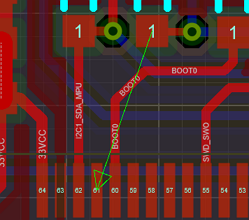
There's still quite a bit of space here but it will be helpful starting point in explaining how push mode works. Let's assume we wanted to move the existing route a little to better connect the remaining track.
1) Start by selecting route placement icon and clicking on the pad to begin routing. The status bar will tell you whether you are in push mode or not.

Switch to push mode (SHIFT+P shortcut) if you are not already in it. You can also see (and change) the mode from the Route Command Centre (keyboard 'R').
2) Move the mouse down from pin 1 and then diagonally along, pushing the existing track out of the way as you go. Go slowly and if you don't like what you see move the mouse backwards and push against a different part of the track. When you've pushed the route sufficiently left click to place an anchor and commit.
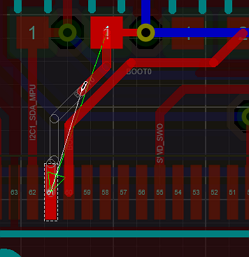
Commit the push with an anchor
This is a really important technique. If you need to push something then go slowly and anchor when you're happy with the push. The push vectors change as you move the mouse so the pushed route(s) will change as well. You can always move the mouse backwards to rewind but it's best to take your time and anchor as you go.
3) Now simply move the mouse along and down to complete the route.
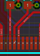
Complete Route after Push
After placing the anchor you could turn push mode off (SHIFT+P) and then simply hug the other track in to make the connection. Selectively turning push mode on and off is very powerful - just remember to place an anchor before you toggle the routing mode!
Let's look at another example where we want to move an existing route along with a via.
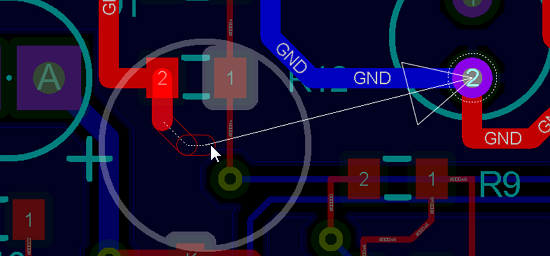
Start of route where we want to connect to GND trace at the right but are blocked.
The shroud around the mouse is called Visual DRC and provides a visual indicator of how close you can get to immovable obstacles. The track to the right of the mouse does not have a clearance because we are in push mode and it is therefore movable.
The procedure is exactly the same. When we start routing, notice that the track and via do not have clearances shown in the Visual DRC circle (see above). Since Visual DRC by defaults shows us clearances around immovable obstacles this means two things:
- We are in Push mode. In FMR mode we can't move anything so everything has clearances shown.
- We can push both the track and via. Sometimes via pushing is turned off (from Route Command Centre) and in that case the via would show it's clearance.
Now we can move the mouse along the bottom of the route to push both the track and the via above the route being placed and free up the route.
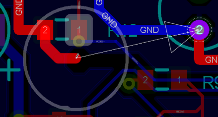
Then we can route to our connecting track and commit.
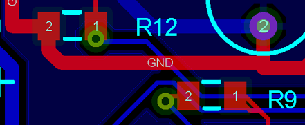
The most important thing to remember about pushing vias is that it affects more than one layer. This means both that it might not be possible because it's blocked and you can't see where but also that you might need to tidy up routes that have been pushed on other layers of the board.
See Also:
Example: Routing Across Two Layers
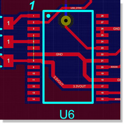
Simple Route needed to connect U6:4 to U6:8
In this example we need to route out from U6:4, drop a via, route under the blocking ground track and then via back through to make the connection. This procedure works in both push mode and FMR mode so it doesn't matter which we're using.
1) Select track mode.

2) Left click on the pad and move the mouse to start routing.
3) Double click the left mouse button to place a via and continue routing on bottom copper.
4) Route under the ground track and double click again to come back to top copper.
5) Route to the track, left click on the track and then right click to finish routing.
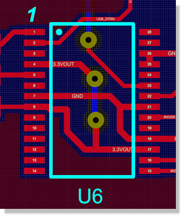
Connection with vias.
Important Concepts
In addition to the technologies used in the first example above, the software does a couple of other things for you in this case. Notably:
- When you double click to place the via, the via style (drill hole, diameter, soldermask, etc.) comes from the Net Classes tab of the Design Rule Manager.
- When you drop the via you switch to routing on a different layer. While a simple decision for a two-layer board, the layer toggle for via's is defined from the Layer Pairs command on the Technology Menu.
- The layer range of the via will be the smallest possible drill range (as defined in the layer stackup) that gets you from the current layer to the associated layer pair. If you have only one drill range then the vias will always be thru-hole but if you set up blind or buried layer ranges and then set up routing layer pairs Proteus will use the best via range automatically. On HDI boards, micro-via drill spans are preferred for adjacent layer transitions.
- When you terminate a connection on a track you must first left click on the centre of a track to complete the route and then right click to exit route placement. This is different from terminating on a pad where a single left click will both complete the track and terminate route placement.
- After completing the track the (GND) plane on bottom copper is punched out to make space for the track. The clearance from the power plane to the via edge is the applicable pad -> trace design rule.
Example: Routing to a Plane Layer
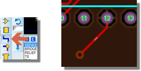
In this example, we want to route from the bypass capacitor down to one our previously specified plane layers. Our procedure is therefore:
1) Select track mode, start routing on the capacitor pin and move a little into free space
2) Double click to drop the via and complete the connection.
Important Concepts
This is an excellent example of where preparation saves a lot of effort during routing. If you have defined a layer stack, specified the plane layers and created your power plane on the plane layer then Proteus is armed with all of the right information. It knows you are routing on the VCC net and it knows there is a VCC plane layer underneath you so when you double click to place a via it understands that you are connecting to the plane layer and can complete the connection for you.
Example: Routing Across Multiple Layers
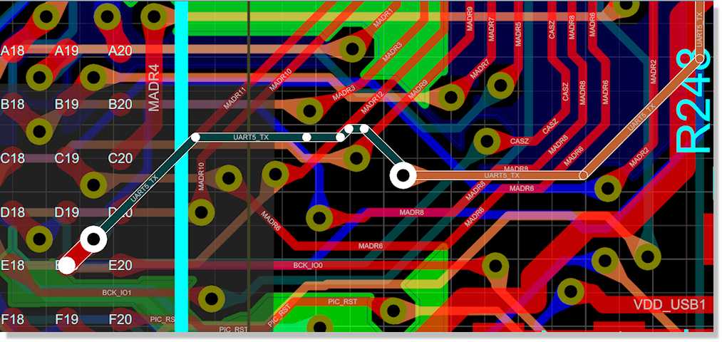
Tracking on multiple signal layers.
Here we have something quite a bit more complex. The main problem is that you don't know which layer to use to escape from the BGA until you are actually placing the route. Once out from the BGA things are still quite crowded and you need control over where on the board your via destination layer is going to be. Use the following process to help with this kind of work .
1) Make sure that you have fully set up your layer stack. In particular, check your drill spans to ensure that you have enough via coverage to escape from the BGA on different layers.
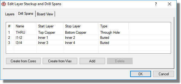
You can launch the Layer Stackup dialogue at any time from the Technology Menu.
2) Setup Layer Pairs. Make default rules for where you are most likely to go when placing a via on a particular layer.
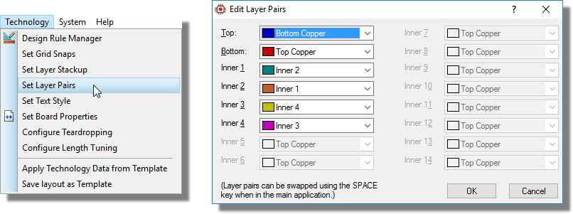
3) Use Push Mode. It's going to be much easier to navigate a dense area of board if adjacent tracks and vias can be nudged a little.
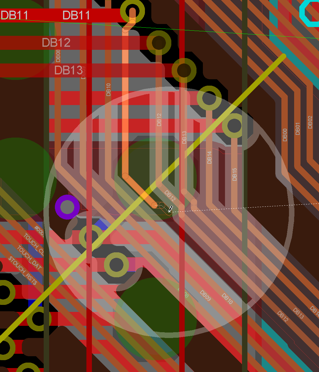
4) Keep or switch Visual DRC on. This will show you where you cannot go due to clearances and also which objects can be moved if need be (those without Visual DRC clearances).
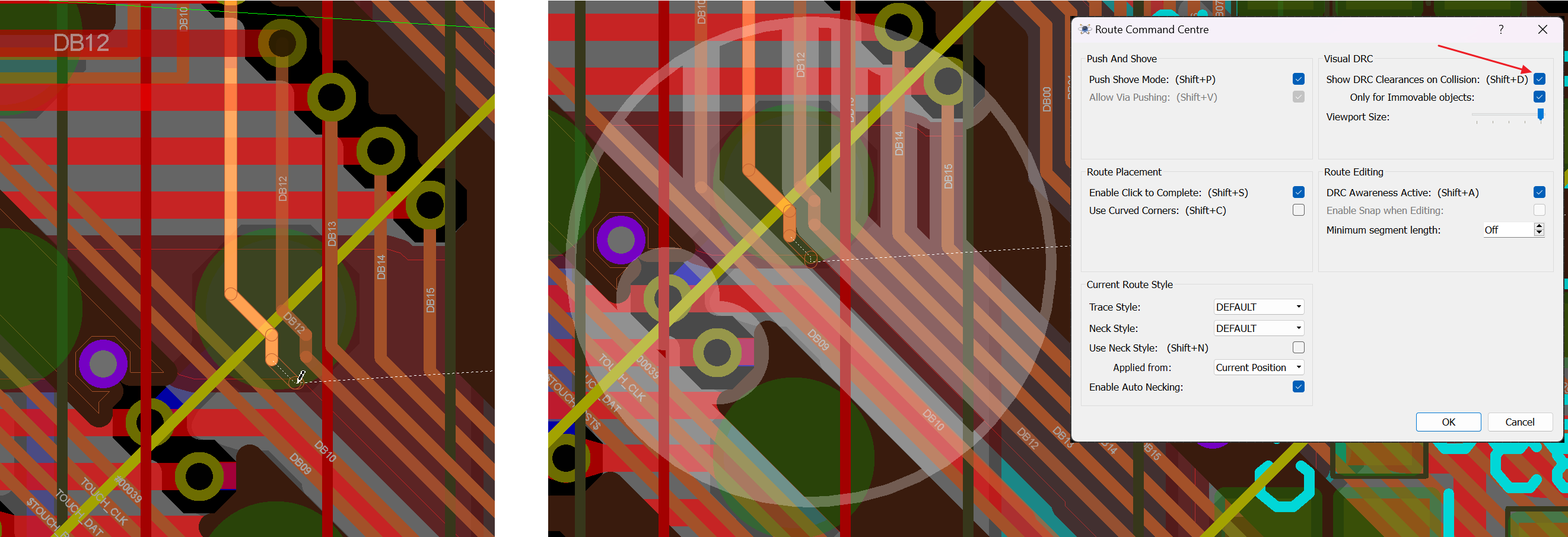
3) Use Floating Vias. When you place a route press the SPACE bar to float a via on the end of the track. PGUP and PGDN then cycle the valid layer destinations for the via in the layer selector, and a left click drops it. With smart vias enabled the best drill span for the destination you settle on is chosen automatically at the end. This takes a little getting used to but has the added benefit of letting you precisely position the floating via before dropping it (it will obey design rules while floating). On HDI boards, if you are inside a DRC room with a micro-via style override the floating via will use the micro-via drill span for adjacent layer transitions; outside a room the shortest CNC span is used instead.
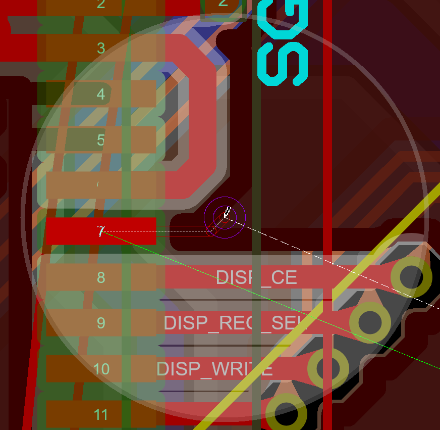
Practise with floating vias until you've mastered the technique. You will end up positioning via's in better places and routing multi-layer tracks far more smoothly.
Example: Dense Routing and Necking
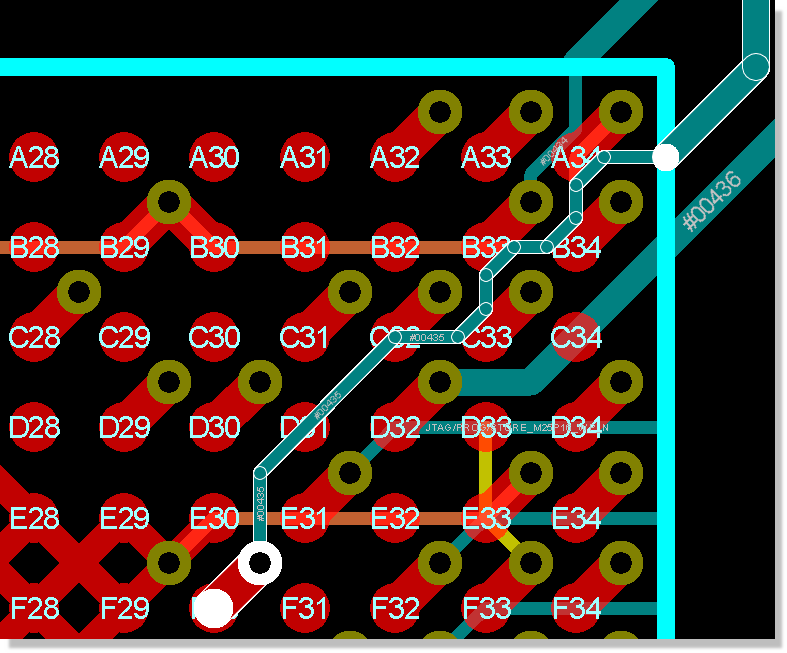
Track necking is needed to escape the BGA.
Here is a classic example of a case where two track widths are needed. The track style is the desired width for the route and neck style is the minimum acceptable width (preferably over small distance). For this kind of routing you need to:
1) Set up design rules carefully. In particular, a tight trace->pad clearance is vital to allow tracks to snake through breakout vias.
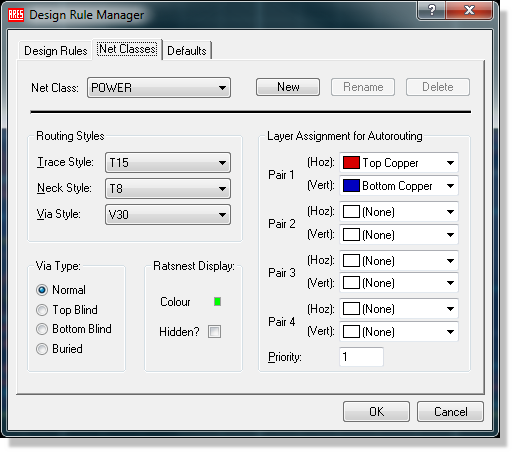
2) Set up net classes carefully. The track, via and neck style for each net class needs to be specified. It may be necessary to create additional track styles or via styles as well.
3) Set layer usage and layer pairs as in the example above. No question this is going to be multi-layer !
4) When routing from the ball use the SPACE bar to float the via, then PGUP and PGDN to cycle the valid layer destinations in the layer selector. Left click to drop the via.
5) Use SHIFT+N to toggle neck style on and off (or launch the Route Command Centre and do manually). In the example above, I switch to neck style at the via (SHIFT button down) and then back to track style on exit from the BGA (SHIFT button released).
The SHIFT key puts you in control over track widths during routing. When space is at a premium or obstacles are preventing you getting through, depress the SHIFT key and try in neck style. It's invaluable with this type of dense routing.
Example: Curved Routing
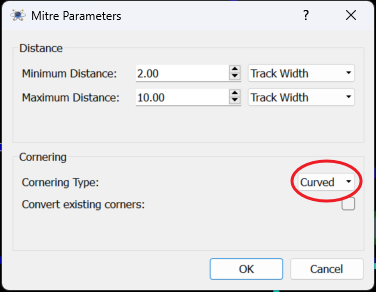
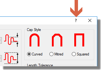
Placing a route with curved corners can be helpful with signal integrity and net tuning or simply for aesthetic reasons. In Proteus, you can only placed curved corners in FMR route (although you can convert them after placement in push mode) and you toggle curved route placement on and off using the SHIFT+C shortcut key (or the Route Command Centre) The process of placing the route is therefore:
1) Left Click the mouse to start the route.
2) Switch to FMR mode if not already there (SHIFT+P).
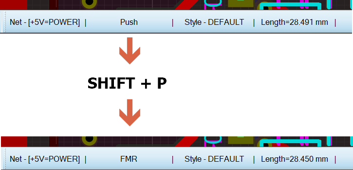
Status Bar shows the current routing mode, changed with SHIFT+P
3) Use SHIFT+C to turn on curved corners or launch the Route Command Centre and configure that way.
4) Route as normal and left click the mouse on the destination pad to terminate the route.
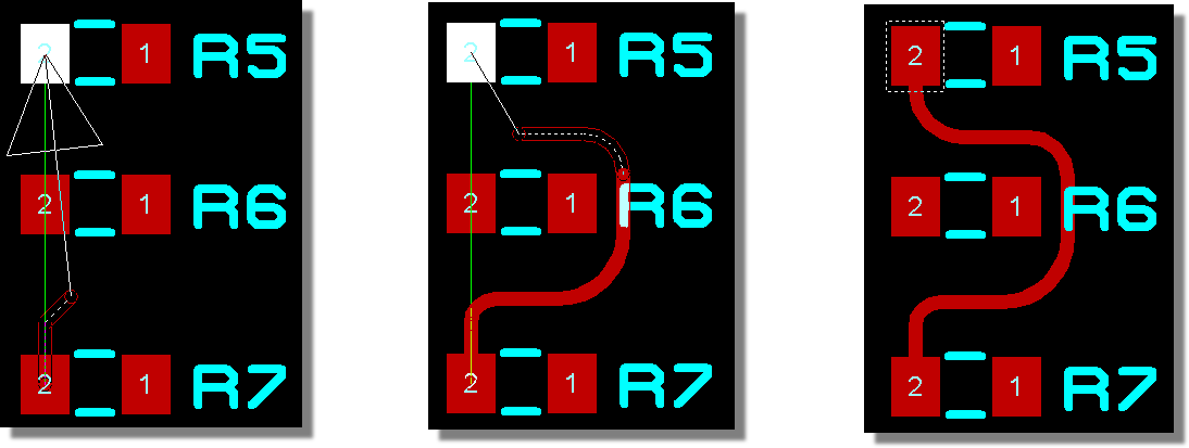
If you need or prefer to route in push mode then you can:
1) Route in push mode with mitred corners.
2) Right click on the completed route and select mitring from the context menu.
3) Change from mitred to curved corners. Space permitting the entire route will change corner style.
Example: Length Matching Routes
Matching the length of routes on the PCB can be essential for signal timing and signal integrity with longer routes and higher speed signals. The process itself in Proteus is extremely simple, namely :
Length matching is available from PCB Level 2 onwards.
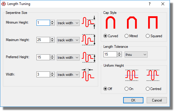
1) Configure the length match settings in the dialogue form (Technology Menu)
2) Route the tracks normally.
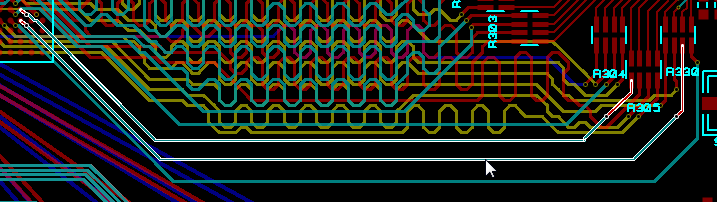
3) Hold the CTRL button down and successfully left click on the completed tracks to highlight them.
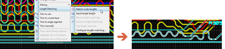
4) Right click on any one of the now selected tracks and choose the length match command from the resulting context menu. Success will be reported on the status bar.
Important Concepts
While the act of matching the lengths is fairly straightforward, choosing the correct topology for length matching can be extremely complex. Issues such as crosstalk coupling, signal distortion and advanced timing all need to be considered with respect the signal rise time. In addition, the PCB land may prove to be an issue (e.g. some patterns will block via sites more than others) and some topologies for matching may not actually be feasible given existing design rules and the presence of other obstacles (pads, tracks,etc.) already on the board.
We strongly recommend that you also read the dialogue level help. There is more detail on each option and the trade-off between them.
Length matching currently works from pin to pin. If you choose to, you can length match across layers and the length of the via(s) will be taken from the layer stack setup. Bear in mind however that using vias is not recommended from a signal integrity viewpoint.
Length matching where a tertiary junction is involved is ambiguous.
Once a matchgroup is formed by matching routes to each other then the software will attempt to maintain it. So, if you edit one of the tracks and change it's length then the others will attempt to match up again within tolerance. This is intended to be a manual operation only though (e.g. to make space) and so length matched tracks cannot be pushed by other tracks.
See Also:
Differential Pair Routing Examples
Example: Via under SMT
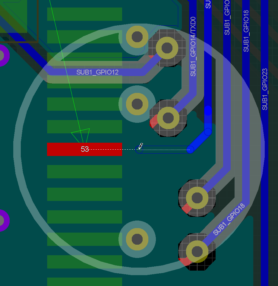
Routing towards connection on the other side of the board.
Here we are routing on bottom copper to terminate on a surface mount pad on top copper. We could via up and then track across in the normal way but we can also via straight up from under the pad to form the connection. So:
1) Route underneath the destination pad.
2) Use SPACE to float a via.
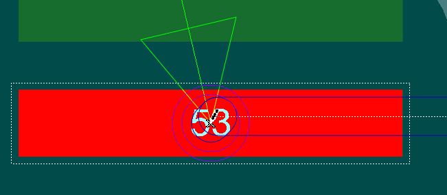
3) You are looking for the pad to brighten to indicate that you are in the contact point (hardware accelerated mode). It's often useful to change snap level up (F3 or F4) as this will snap you onto the centre of the pad.
4) Left click to commit placement and complete the route. You'll know when it's connected because the ratsnest line will disappear.
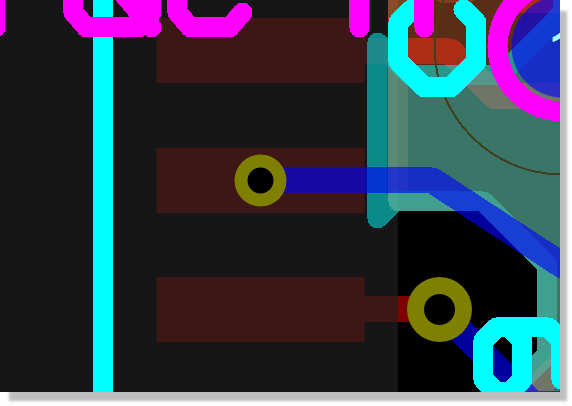
Completing the route by via-under-smt.
You may then want to specify the via(s) as resin filled for manufacture.
Example: Escaping a BGA on an HDI Board
This example covers BGA escape routing on an HDI (1+N+1) board using micro-vias. The setup assumes:
- A layer stackup with at least one micro-via drill span defined (e.g. Top Copper ↔ Inner 1).
- A micro-via pad style has been created (e.g. with a 0.1 mm hole and 0.25 mm pad).
- A DRC room has been placed over the BGA area with the micro-via style selected as the via style override and the Use Microvia checkbox enabled.
- Net classes are configured for smart via mode (the default).
- Layer pairs are configured so that Top Copper is paired with Inner 1 (or whichever layer is adjacent through the buildup dielectric).
The procedure is as follows:
1) Select track mode and left click on an inner ball of the BGA to start routing.
2) Route outward from the ball. Since you are inside the DRC room, the via style will automatically be overridden to your micro-via style.
3) Double click to place a via at the desired escape location. Because the layer pair defines an adjacent layer transition and there is a micro-via drill span in the stackup, Proteus will automatically select the micro-via drill span and (because you are inside the DRC room) the micro-via pad style. Routing continues on the paired layer.
4) Continue routing on the inner layer to reach the destination. If you need to come back up through the buildup layer, double click again to place another micro-via and return to the top layer.
On a 1+N+1 board the layer pair defines the via transition unambiguously, so double click is the most efficient way to place micro-vias during escape routing. The SPACE bar floating via is better suited to stackups with multiple destination layer choices where you need to select a specific layer manually.
Outside a DRC room, the smart via algorithm excludes laser drill spans entirely and will select the shortest legal CNC span instead (normally a plated through-hole). Inside a room, if the layer transition is incompatible with the room's micro-via style (e.g. it spans more than one dielectric), the override is not applied and the net class default CNC style is used, with a one-shot warning on the status bar. See Via Style Defaults on HDI Boards for a full explanation.
Micro-vias are always copper filled as part of the HDI fabrication process. There is no need to set via filling separately for micro-vias.
See Also:
Via Styles (Standard and Micro-Via)