USING POWER PLANES
Overview
There are two alternative ways of using the polygonal power plane functionality:
- Using the Power Plane Generator command either directly on the Tools Menu or from the Layer Stack Manager.
- Using the Zone icon you can place rectangular or polygonal regions of copper which can form arbitrarily shaped ground planes occupying any chosen region of the board.
In both cases, the zones can be assigned to be hatched or solid, and computed with boundary tracks of specified thickness. There are however some differences between the two methods, explained in detail in the following topics and summarised in brief below:
| Scenario | Power Plane Generator | Zone Icon - Manual Placement |
| Defining a plane that covers a plane layer |  |
 |
| Defining a partial/split plane on a plane layer | |
|
| Defining a plane that covers a signal layer | |
|
| Defining a plane that covers part of a signal layer | |
|
| Defining a plane that is 'locked' to the board edge | |
|
| Defining a keep-out area inside an existing plane. For a keep-out that is DRC enforced and covers several layers at once, use an exclude foreign design room instead. | |
|
The Power Plane Generator Command
This command provides the simplest way to create a power plane and causes the generation of a single power plane object occupying the entire area of a given layer of the board.
To use the Power Plane Generator command:
- Choose a net for the power plane. If no net is specified, the power plane will connect to any pads which are marked for Thermal or Solid connection.
- Choose a layer for the power plane.
- Choose a boundary style for the power plane.
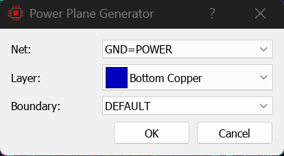
The Power Plane Generator dialogue
Proteus will then generate the power plane, and update the ratsnest display to show the effect on connectivity.
The power plane will step away from the edge of the board by the amount specified in the design rule manager for edge clearance. Since this value is rule specific and you can create single layer design rules it follows that you can define different edge clearances for power planes on different layers.
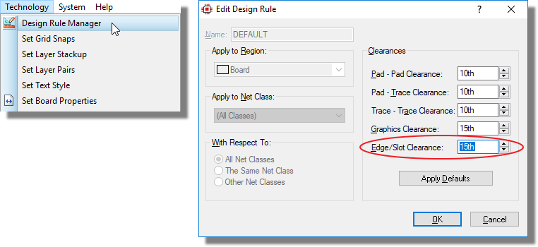
The edge clearance in the Design Rule Manager sets how far the plane steps back from the board edge
Planes generated with the Power plane generator are considered locked to the board edge (stepped away by the clearance amount) and will automatically maintain their distance from the board edge if it is moved or adjusted.
See Also:
Power Planes and Slots (Tutorial)
Zone Placement Mode
The most flexible and powerful way to use the polygonal power plane functionality is to use the zone placement mode.
To manually place a power plane:
- Select the Zone icon.
- Select the required layer using the Layer Selector.
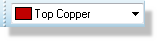
- Either:
- Drag out a rectangular power plane by clicking and dragging from one corner to another with the left mouse button depressed.
Or:
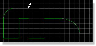
- Mark a polygonal power plane by clicking left at each vertex. In this mode, you can also hold down the CTRL key to place curved sections of boundary.
- Proteus will then pop up the Edit Zone dialogue enabling you to choose a net and fill style for the zone.
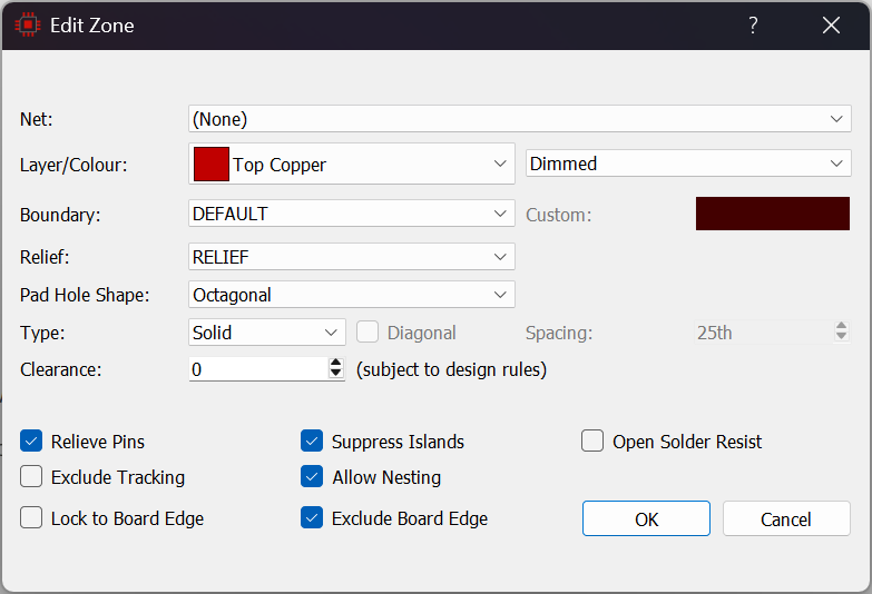
- When you click OK, Proteus will generate the power plane and update the ratsnest display to show its effect on connectivity.
Regardless of the mode of zone creation you can increase the transparency of the zone (dimming) from the Custom combo on the Edit Zone dialogue, whose settings are Normal, Dimmed and Custom.
See Also:
Power Plane Generator Dialogue
Plane Layers
A plane layer in Proteus is a copper layer intended to carry no tracking. It is specified in the Layer Stackup manager on the Technology Menu or during project setup in the New Project Wizard. Proteus does not physically prevent you placing a track on a plane layer, but the pre-production check will report it with a Tracking found on plane layer warning. Plane layers are also excluded from layer pair toggling while routing.
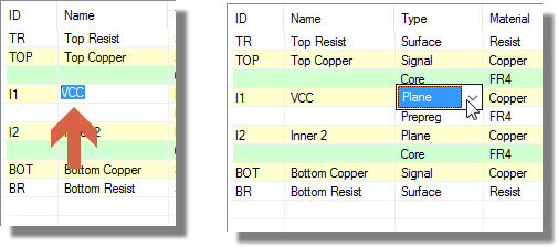
Configuring a Plane Layer in Layer Stackup (1)
If you are in the New Project Wizard then the Create Power Plane button will be disabled. This is because the power plane generation requires the plane to be assigned to a net and to be placed inside a board edge, neither of which are available at this stage. Once the board edge has been created and the netlist transferred from the schematic you can add the power plane to the layer by revisiting the stackup manager or using the power plane generation tool described above.
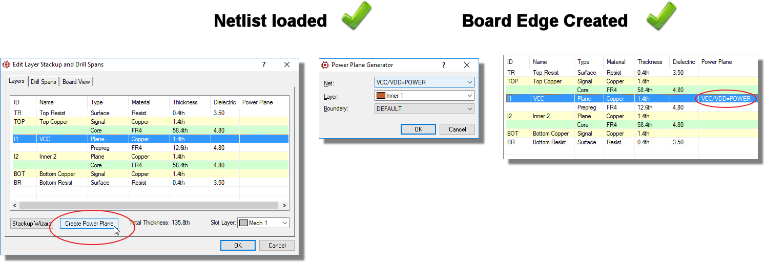
Configuring a Plane Layer in Layer Stackup (2)
Why Use Plane Layers ?
The main benefit of specifying plane layers is that during routing, Proteus understands how to make the connection to the plane. During manual routing, Proteus will compare the net of the track to the net of the planes on plane layers and automatically make a connection on double click. Similarly, the autorouter will via through to planes on the plane layer in order to form connections.
See Also:
Manual Routing Examples : Routing to a Plane Layer
Power Planes and Design Rules
The clearance between a power plane and an object is the largest of three values:
- Currently enforced design rule for the object.
- Clearance field in the zone dialogue.
- Specific pad clearance in edit pin dialogue (pads only).
Since the clearance field in the zone dialogue defaults to 0th and the specific pad clearance is also 0th (intended for mounting holes) the normal behaviour for power planes is that they will step away from objects according to the design rules. This works because any border of the zone is treated as a trace for the purposes of design rule clearances.
Three clearance values are relevant:
-
Pad->Trace: The clearance around each pad / via and the zone.
-
Trace->Trace: The clearance between a trace and the zone.
-
Edge/Slot: The step off that the zone takes from the board edge.
If you really need the same clearances across the entire power plane and you have different design rules in force you can set a clearance for the zone via the edit zone dialogue form. This normally happens when you have a zone covering a layer and you then have a design room inside the layer, meaning different rules apply in different areas of the power plane. Bear in mind that the largest (safest) value will be applied wherever there is a duality so to ensure that the clearance field is the one used across the power plane you will need to set it's value higher than that used in the design rules.
The simplest and most verifiable method to handle clearances around planes is to do it entirely within the design rule system using the clearances described above. You can set up multiple rules for different layers, nets or even use design rooms for area based clearances. This will then feed into the live verification system as well as the pre-production check and the design rule report for design documentation.
To comply with the pad to plane clearance requirements of IPC-2221 (Table 9-2), take the required gap from the standard and enter it as the Pad->Trace clearance of a design rule scoped to the plane layer or to the plane's net class.
See Also:
Editing a Power Plane
Power planes are held as zone objects which behave similarly to other objects on the layout.
To edit a zone:
- Select the Zone icon.
- Select the zone's layer using the Layer Selector.
- Click right then left somewhere on the zone boundary to tag then edit the zone.
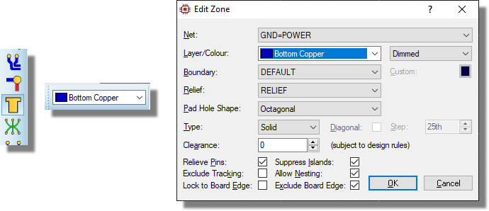
Editing a Power plane
Context Sensitive Help is available for all the fields within the Edit Zone dialogue form, and the whole dialogue is documented under Edit Zone. Two of its settings are worth knowing about before you start:
- Relieve Pins decides how every pad whose own relief setting is left at Default connects to the zone: ticked gives a thermal relief, cleared gives a solid connection. It is the fallback behind every pad you have not overridden individually.
- Exclude Tracking and Exclude Board Edge control whether the flood avoids existing tracking on the layer and whether it steps away from the board outline. Lock to Board Edge keeps the plane a fixed distance from the outline as the outline is edited.
Some fields are only available for some zone types. Spacing and Diagonal apply to hatched zones only; Lock to Board Edge and Exclude Board Edge apply to solid and hatched zones; and an Empty zone disables Net, Clearance and Open Solder Resist altogether.
You can also Edit Planes directly from the Zone Inspector dialogue form.
See Also:
Nesting and Islands (Tutorial)
Deleting a Power Plane
This is very simple since the zone is a self contained object 'owning' all the copper regions within its boundary:
To delete a zone:
- Select the Zone icon.
- Select the zone's layer using the Layer Selector.
- Click right twice somewhere on the zone boundary to delete the zone.
Stitching two Power Planes Together
Via stitching is a technique used to tie together larger copper areas on different layers, helping keep return paths short and to reduce noise on the PCB. To stitch planes in Proteus right click on the border of the zone and select Via stitch from the context menu. You then set the zone to stitch to and the spacing and offsets for the vias. The companion command for shielding a zone or a route is Via shield.
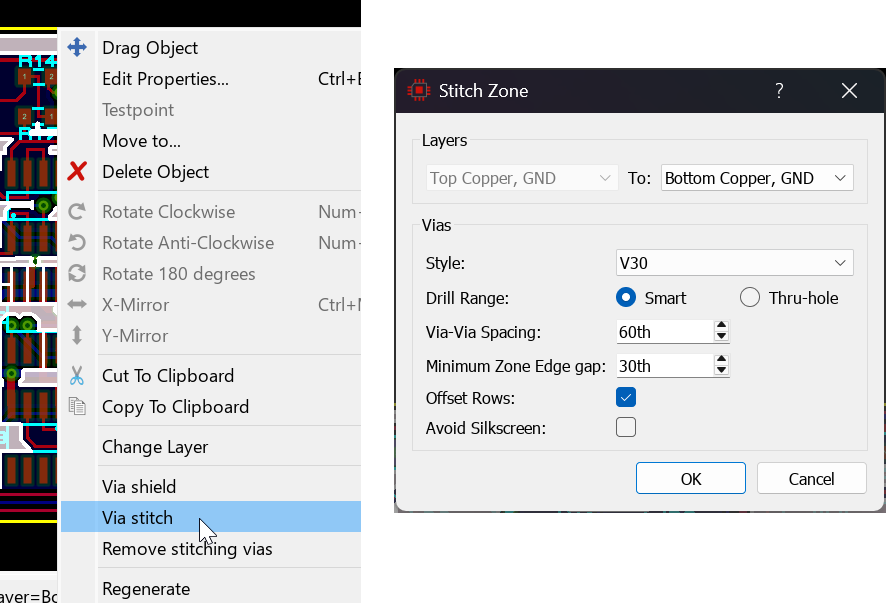
Choosing Via stitch from the zone context menu and setting up the via grid
Once placed you can move and edit vias in the normal way. You can remove groups of vias with a selection box and the selection filter or you can remove all stitching vias with the Remove stitching vias command on the zone context menu.
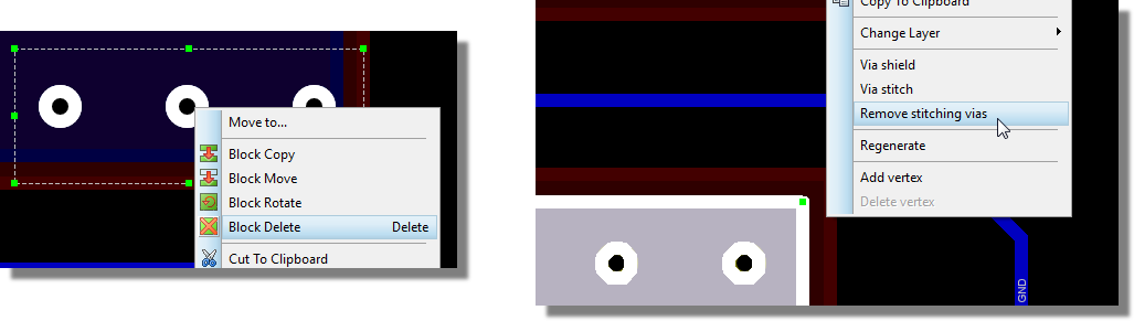
Removing stitching vias from a zone
Stitching zones is something to be done towards the end of development because it will render the board almost un-routable.
If you receive an error message in the status bar then you have selected the wrong zone to remove the vias from. When the stitching vias or shield vias are placed, they are assigned to the zone stated in the left hand side of the form:
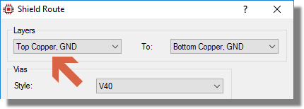
The owning zone is named on the left hand side of the stitching form
If you select a zone that does not 'own' any stitching vias and select Remove stitching vias, you will receive the following error in the status bar:

The status bar error shown when the selected zone owns no stitching vias
The Zone Inspector will list the number of stitching (or shielding) vias associated with a plane.
See Also:
Example: Stitching two zones together
Exposing Solder Resist
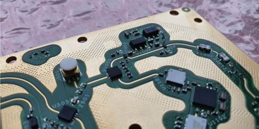
Exposing resist plane to ensure good contact with custom Aluminium case with cavity for RF isolation purposes.
You can choose to open the solder resist (solder mask) around an entire power plane via the Open Solder Resist checkbox on the Edit Zone dialogue form. This is unlikely to be used often but, given the complex polygons involved in most copper pours, is a huge timesaver when needed.
The option is constrained. It only takes effect on the outer layers, opening the top resist for a zone on Top Copper and the bottom resist for a zone on Bottom Copper, and only for solid or hatched zones. It has no effect on inner layers, and the checkbox is disabled outright for an Empty zone.
If you need to open the resist around a track you can do so with a graphic line of the correct thickness on the appropriate resist layer.
It's really helpful to use the 3D Viewer to visualise the solder resist openings on your board.
See Also:
Automatic Regeneration of Power Planes
Use this to speed up work when zone regeneration is slow on complex boards. Full zone regen must then be turned back on before generating output files.
If you place, move or delete tracking or vias onto a board containing one or more power planes, Proteus detects whether the power plane needs to be regenerated and then either:
- Proceeds to recompute the internal boundaries of the zone immediately. On a fast PC and a board of low to medium complexity this real time update mode of working can be quite viable with regen times of the order of 1 or 2 seconds. Complex zones are regenerated on a background thread so that you can carry on editing; the zone is drawn in hatched form while its regeneration is pending and redraws as soon as the regen process completes. The Background Regen. Threshold field in the Zone Configuration dialogue (System > Set Zone Operation) determines the number of holes required in a zone for it to be deemed complex and thus processed using background regens.
or:
- Redraws the zone in hatched form to show that it is invalid. In this case an invalid zone is regenerated by right clicking on it and selecting Regenerate from the context menu. This mode saves much frustration if the zone regen times are rather long, as will be the case on slower PCs or with complex boards.
You can toggle auto regeneration on and off using the Auto Zone Regeneration command on the Tools menu, default keyboard shortcut CTRL+R.
Quick Draw Zones
When a zone is drawn 'properly', all the external and internal polygon boundaries are drawn in tracking of the specified style. However, this can be quite time consuming and so a Quick Draw Zones option is provided in which
- The polygon boundaries are not drawn at all.
- Thermal relief segments are drawn as single pixel lines.
- If the zone is hatched, then the hatching lines are drawn as single pixel lines.
Quick Draw Zones, and also the zone auto-regen feature, are editable from System > Set Zone Operation, which opens the Zone Configuration dialogue. Both settings can be saved in the configuration file by invoking the Save Preferences command.
Quick Draw Zones is disabled by default.
See Also:
Auto-Routing & Power Planes
In general, it is best to place power planes prior to auto-routing. There are two principal reasons:
- The power plane will make connections to any through hole pads within itself, and this will remove the need for the autorouter to do so.
- Planes that exist at the time the design is handed to the autorouter are declared to it as plane layers, so the router knows it can drop a via straight into them to make a connection. In the case of SMT components this is what lets the router escape a pad to the plane, so it is essential that the zones be placed prior to routing on plane layers if you wish the router to auto-via to them.
In cases where the power plane is on a layer shared with other tracking, the power plane may become split by tracking placed by the router. In this case, some ratsnest lines may be left at the end of the routing pass, and the best thing to do is to re-run the auto-router in order to complete these by conventional tracking.