OBJECT PLACEMENT
Overview
The objects you place on the layout are:
- Components and packages
- Pads and pad stacks
- Tracks, differential pairs and vias
- Zones
- Rooms
- 2D graphics, text, symbols, markers and dimension objects
This topic covers the objects you place directly. Tracks and vias are placed while routing and are covered in Route Placement and Editing and Vias; rooms are covered in Design Rule Rooms and Auto-Placement. Everything else is placed in much the same way although there are some slight differences which are detailed in the following sections.
Placing Components
Proteus draws a distinction between Components and Packages in that a component is a part specified in the netlist whereas a package is not linked to the netlist, has no part ID, and plays no part in netlist driven design verification / modification. Assuming you are using a netlist, 99% of the parts you place would usually be components. You would only use packages for parts which, for whatever reason, were not entered on the schematic. Heatsinks are the most common example of this. If a netlist is in use, parts which are not specified in it must not be given names.
To place a component
-
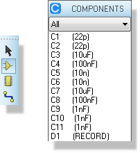
Select the Component icon from the Mode Selector toolbar. In this mode, the Object Selector lists all components not yet placed.
-
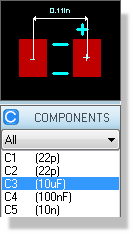
Choose the component you want to place from the Object Selector.
-
Set the Rotation and Mirror icons to determine the required orientation.
You can set the rotation to non-orthogonal angles by typing into the text edit-box.
-
Set the Layer Selector to determine the required layer. Note that the Layer Selector and the Mirror icon are interlocked, since a reflected component must be on the underside of the board.
-
Point at the desired position for the component on the board and left click the mouse.
-
Move the mouse to the desired location. A 'shadow' component will follow the mouse at this stage.
The '+' and '-' keys on the numeric keypad will rotate the component anticlockwise and clockwise respectively in steps of 90 degrees. -
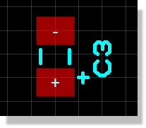
When the mouse is over the location that you wish to place the component left click again to drop the component at this point and exit placement mode.
See Also:
Placing Components and the Ratsnest (Tutorial)
After placement, you can edit the component and choose to hide an individual component reference or value. This is often useful in high density areas of a PCB where routing space is at a premium.
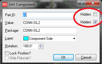
Local options to hide part reference and value text.
You can also lock the component in place, preventing accidental movement during board layout. All components which have been locked are shown with a padlock beside them when in selection mode making them easy to find and unlock if need be.
A placed component can be added to a group straight after placement, and a group then moves as a single unit. See Object Editing for grouping.
Note that this is a local override of the global settings. You can control visibility of part references globally via the Set Text Style Command on the Technology Menu. If you make a local change then the part will be unaffected by subsequent changes to global text styles (e.g. fonts).
Components on the underside of the board
When a component is placed on the solder side of the board, it is effectively 'turned over'. This means that it suffers both a reflection in 2D space and an inversion of the layers of its pads. More specifically:
- The silk screen legend moves from the Top Silk Screen to the Bottom Silk Screen.
- Pads on the Top Layer only, move to the Bottom Layer and vice versa. This caters for underside placement of surface mount components.
- Pads on multiple layers, most commonly normal through hole pads, are left alone, and padstacks are left alone by default. On the assumption that a padstack has been defined in a particular way to reflect the usage (signal, ground plane, etc.) of a particular layer, it would be unhelpful to invert pad stacks for solder side placements. If you do want a padstack to invert, tick Swap for solder side placement in the Outer Layers Flipping group of the pad stack editor.
You can also place components programmatically via the Goto Position command (View Menu).
Once placed you can move components programmatically via the Move to command on the right click context menu. By default the Use Origin of Object? checkbox is ticked, so the co-ordinates you enter move the part origin. Untick it to move pin 1 of the part instead. Note that the part origin may in fact be pin 1.
The Move to command behaves differently for a multiple selection. The selection variant of the dialogue has X and Y fields only and no origin checkbox, so the whole selection is moved as a block.
Placing Packages
As discussed above, the term Package is used to refer to a placed library part which has pins but is not linked to the netlist. On the layout, they are useful in the following circumstances:
- If no netlist is available, or you are doing a simple 'quick and dirty' job, you can lay out a board by placing packages and wiring them up using traces and vias. In doing this, you are using the layout module as a computerised light box, rather than as a true EDA tool.
- Occasionally you might need to place objects which have pads and graphics but are not actually components in the electrical sense of the word. Heatsinks with mounting holes are an example of this. These can be placed as unlabelled packages, and as such, will play no part in the netlist driven functions of the design work.
- In order to edit a library-package, it is necessary to place it as a package, tag it and then decompose it using the Decompose commands. The individual elements can then be edited as required prior to re-making the library-package using the Make Package command.
You do not generally want to be working with packages at all in a commercial design process. Components are linked to schematic parts, providing net class and connectivity data whereas packages are just land patterns.
To place a package
-
Select the Package icon from the Mode Selector toolbar. In this mode, the Object Selector lists all the packages picked from the libraries.
-
Assuming that the package you want has not yet been picked from the libraries, click the Pick from Libraries button at the top of the Object Selector.
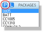
-
Pick the package or packages you want from the Library Pick Form.
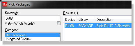
-
When you have finished picking packages, close the form in the usual way.
-
Highlight the package you want to place in the Object Selector.
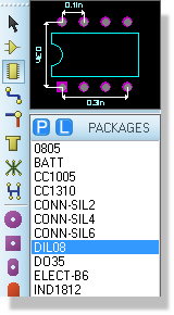
-
Proceed from step [3] in To Place a Component above.
A practical example on creating footprints can be found in the appendix to the tutorial.
Placing Pads
The main reason for placing lone pads is when defining a new library-package but they are also useful for test points, drilling alignment targets and mounting holes. The Proteus layout module offers seven shapes of pad: Round Through-hole, Square Through-hole, DIL, Edge Connector, Circular SMT, Rectangular SMT and Polygonal SMT. See Pad Styles for a full description of each.
In addition, Proteus supports pad stacks, in which a different pad shape can appear on each layer of the board.
The various pad shapes may be selected from the Mode Selector toolbar.
Given the selection of a pad shape, an actual pad style of that shape may be selected from the Object Selector. You'll see that all the pad styles have names. This is a unique feature of Proteus and has two advantages over other systems:
- There is less chance of confusion or error when choosing a style (provided that you use sensible names!).
- There is no limit to the number of styles you can have.
Pads are placed in much the same way as components and packages. The Rotation icons affect the placement of DIL, SMT and Edge Connector pads whilst the Layer Selector again determines the layer set of the pads.
You can edit a pad style by selecting it in the Object Selector and then clicking the Edit button. Any changes to the pad dimensions take effect as soon as the display is redrawn and you can force a redraw with the Redraw command. This feature is particularly powerful should you find the need to tweak pad styles globally in order, for instance, to change the pad sizes used in the standard package library.
You can also place loose pads and then manually attach them to a net. This is particularly useful for RF work where you want to stitch zones together for example. After placement, simply tag and edit in the normal way and select the appropriate net from the resulting dialogue form.
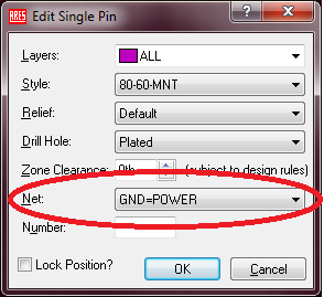
Assigning a Pad to a Net
You can also place pads programmatically via the Goto Position command (View Menu). This will work with either X-Y or R-Theta, depending on your currently specified co-ordinate system.
See Also:
Example: Customising Relief on a Power Plane.
Example: Specifying Minimum Clearance from a Power Plane.
Placing 2D Graphics
The 2D drawing facilities are intended, in the main, for adding text and graphics to the silk screen layers though they can also be placed on other layers by first selecting the desired layer from the Layer Selector. Objects placed on the Edge layer appear on artwork produced from any of the other layers making it a suitable location to draw the board outline.
There are 9 types of standard 2D graphic object, namely:
- Line
- Box
- Circle
- Arc
- Path
- Text
- Symbol
- Marker
- Dimension Graphic Object
Lines are drawn by clicking left at each end.
Boxes and circles are placed by left clicking once and then dragging out the desired area, left clicking a second time to commit placement.
Arcs are placed by drawing a quadrant in the same manner as for a box or circle. They can be further adjusted by tagging and dragging the four handles.
Paths are closed figures with boundaries defined as multiple line and arc segments. Click left at each required vertex and hold the CTRL key down to place arc sections. Further adjustments may be made by tagging the path and moving the green ‘handles’ about. We strongly recommend that paths are not used to create copper fills as they are not recognised by the connectivity database. Use zones instead.
Text is placed by clicking once on the Editing Window at the point where you want the text to appear. A form then appears which allows input of the text itself and also allows control of the text dimensions. Text orientation can be set using the Rotation and Mirror Icons.
Selecting the Symbol icon displays symbols in the Object Selector. Symbol selection is identical to package selection as described earlier. More information on the symbol library facility is contained in The Symbol Library.
Markers are used in the creation of library parts to define the origin, and also the position for component labels.
Lines (end points), Boxes (length and width), Circles (radius) and Arcs (end points) can be given specific dimensions once the graphic has been placed. Simply edit the graphic and change the dimensions as preferred:
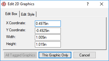
Setting the dimensions of a 2D graphic.
This does not work for already created packages.
You should always use a 2D Graphics Path or 2D Graphics Box to form your board edge. It is important for the software to know the bounds of the board in order to limit copper flow, auto-routing and auto-placement.
See Also:
Dimension Graphic Object
The dimension graphic object is a useful tool for sizing objects and positioning objects relative to one another. You place it exactly like placing a 2D graphics line but it will display the length of the line drawn on completion. This provides an easy and convenient way to take measurements on the layout. By editing the dimension object in the usual way (see Editing an Object) you can specify which units you want displayed according to the options given below:
| Syntax | Description |
|
%A |
Automatic Mode. This is the default mode and will use the units currently specified in the layout module. |
|
%M |
This syntax specifies that the units for the dimension graphic object are millimetres |
|
%C |
Specifies units of centimetres for the dimension graphic object. |
|
%T |
Specifies units of thou for the dimension graphic object |
|
%I |
Specifies units of Inches for the dimension graphic object. |
|
%B |
Best fit. The dimension is auto-formatted, so Proteus chooses the unit and the number of decimal places that suit the measured length. |
Note that, with the exception of Automatic mode, you can append unit specifiers to the syntax. In the example below the units are entered as millimetres and suffixed with the standard unit specifier.
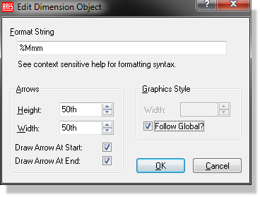
Dimension settings
Placing Zones
Zones represent the means by which Proteus handles power planes. In this section we will just describe briefly how to place a simple power plane; further documentation on power planes is given under Power Planes .
To place a power plane on a layer
- Make sure that you have specified a board edge. This is necessary to bound the area into which the zone will be drawn. To do this draw a board outline of the correct dimensions using the 2D graphics tools on the Board Edge layer. Ensure that the boundary forms a closed polygon. The best way to do this is to use a Path object.
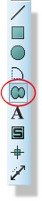
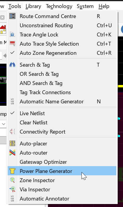
- Select the Power Plane Generator tool from the Tools Menu.
- Set the three combos on the dialogue form: Net, Layer and Boundary, the last of these being the trace style used for the zone boundary. Each of these options has context sensitive help available direct from the dialogue form. The zone is generated from the board boundary path, and its clearance from the board edge comes from the design rules rather than from this form.
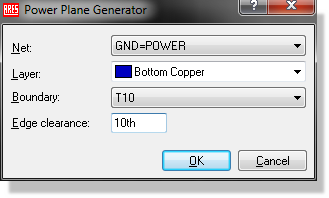
- Hit the OK button to render the zone with the specified options.
To place a polygonal or partial power plane.
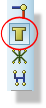
- Select the Zone icon from the Mode Selector toolbar.
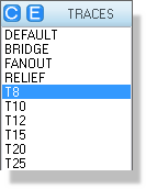
- Select the required boundary trace style for the zone from the Object Selector.
- To define the zone boundary, either:
- Drag out a box with the left mouse button held down.
- Click at several points to form a polygonal boundary.
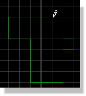
If a zone boundary is placed over existing tracking, it will pick up its net from that tracking. This makes it quite easy to place lots of small zones in order to ‘fill in’ between tracks.
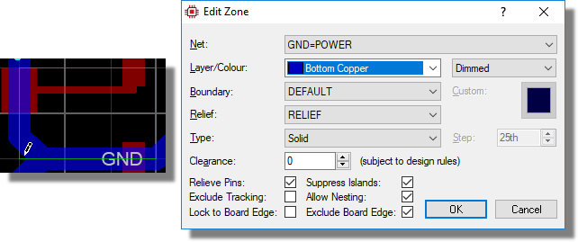
- Select the required net and hatch/fill style from the Edit Zone dialogue form, then click OK.
- Proteus will generate the ground plane
See Also: