As signal speeds get faster and operating currents lower, the integrity of the signal becomes an increasingly necessary consideration during PCB Design. In particular, the transit time of signals often needs to be synchronized by matching the copper length of the traces on the PCB.
Aside from more general requirements such as layer stackup and design rules, Proteus support for high speed design starts with serpentine routing. This allows the user to automatically length match routes to each other or to target distances. This technology is then coupled with advanced design rules and a dedicated routing mode to support differential pairs. When needed, differential pairs are automatically phase matched (skew reduction) to keep the signals equal and opposite for as much of the transit time as possible.
- Full support for length matching and serpentine configuration.
- Net tuning and match groups including daisy chain/shared segment configuration.
- Differential pairs with dedicated routing mode and automatic phase matching.
- Detailed length match reporting and differential pair reporting.
Length Matching
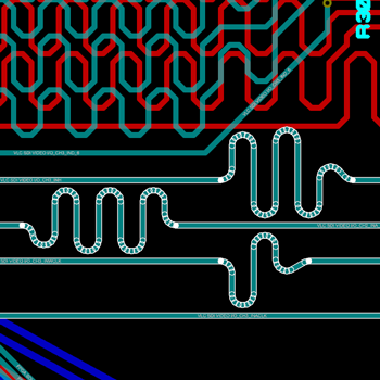
Technical brochureLength matching of tracks is an essential step in ensuring correct timing at the signal receiver for high speed transmissions. Proteus PCB Design includes support for automatic length matching of tracks via a simple select and match user interface. This includes the ability to have track segments in multiple match groups which is needed for routing topologies like the DDR3 fly-by configuration.
Much of the difficulty with length matching lies in the arrangement of the extra trace used to lengthen the shorter routes (often called the serpentine). Depending on the signal rise time, the frequency of the signal, the requirement for via sites on the PCB and many other factors the PCB designer may need to adjust or constrain serpentine height and width. In Proteus, this is all handled via a single dialogue form where the topology of the serpentine can be controlled. You can also adjust either an absolute or a relative tolerance for the length match according to the timing budget for your interface.
For large BGAs the internal signal distance can be added to the component as a CSV file and a length match report can be generated at any time.
Automatic length matching or net tuning requires Proteus PCB Design Level 2 or higher.
Internal Lengths
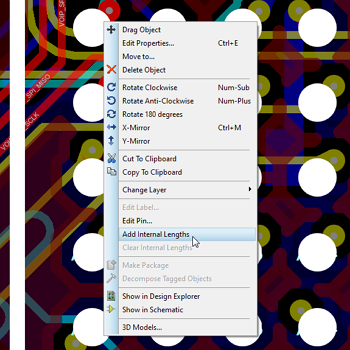
When length matching extremely sensitive signals the internal distance from the contact point of the lead on the PCB to the component can become significant enough to affect calculations. Proteus allows you to specify this distance via the INTERNALLENGTH property of the footprint itself. Similarly, if the connection length of a passive used in the middle of a differential pair needs to be considered you can add a CONNECTIONLENGTH property to the footprint. Finally, if vias are used in the routes the barrel depth between the layers is calculated from the layer stackup definitions
These distances will be added to the etched copper distance in the length matching algorithm to ensure that the routes match inside tolerance.
Automatic length matching or net tuning requires Proteus PCB Design Level 2 or higher.
Micro-Vias
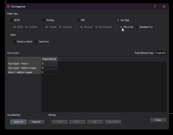
Learn more about Micro-ViasHigh Density Interconnect (HDI) boards use laser-drilled micro-vias to achieve the component densities required by modern high speed interfaces. Proteus 9.2 introduces full HDI support with a 1+n+1 board style in the Stackup Wizard, and micro-vias integrate directly with the length matching system so that signal integrity calculations remain accurate on HDI designs.
Because micro-vias are laser-drilled and span only a single build-up dielectric layer, their barrel depth is significantly shorter than that of a conventional through-hole or buried via. Proteus calculates via barrel length from the declared dielectric thickness in the layer stackup and adds it automatically to the total route length for each net. This means that when length matching DDR, PCIe or other high speed interfaces on an HDI board, the shorter micro-via contribution is accounted for correctly without any manual adjustment.
From a signal integrity perspective, a shorter via stub reduces the parasitic capacitance and the resonant stub effect that can corrupt high speed signals. Routing the first layer transition on an HDI board as a micro-via rather than a full through-hole via — for example when escaping a fine-pitch BGA — keeps stubs short and improves signal quality at high data rates.
Differential pair routing is fully compatible with micro-via spans. The smart via logic selects the shortest available drill span for each layer transition, preferring a laser-drilled micro-via span when the source and destination layers are covered by one. Phase matching and skew correction operate on the resulting routes in the normal way, so differential pairs routed through micro-via transitions remain within tolerance without any additional steps.
Differential Pair Setup
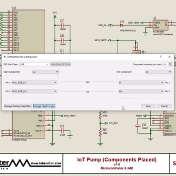
Defining the differential pairs on the schematic and configuring the signal path from source to destination through in-line passives can be both time consuming and error prone. The differential pair configurator in Proteus provides a dialog based solution to this, along with a clear visual indication that the differential pair is set up correctly.Pass through components are fully supported in the configurator, including multiple passives on a diff pair signal line.
Differential pairs routing requires Proteus PCB Design Level 2 or higher.
Differential Pair Routing
Proteus PCB Design supports differential pairs both through the design rule system and with a dedicated routing mode. Advanced design rules let the user specify clearances between the routed pair as well as letting you define maximum unpaired lengths and phase tolerance criteria.
Meanwhile, with the differential pair routing mode you simply click on one of the source pads and route to the destination with both tracks routing at the same time. With BGAs where you have a controlled fanout you can route them normally and then switch to diff pair routing mode and start from the fanout vias. The routing is fully design rule aware and you can switch in and out of curved routing mode simply by holding the CTRL button down. Finally, differential pairs can themselves be length matched either to other pairs or to a target distance via a context menu command.
Differential pairs routing requires Proteus PCB Design Level 2 or higher.
Pass Through Components
It's fairly common with differential pair topologies for a passive device to sit on the transmission lines. This could be anything from little ESD diodes on USB lines to a choke or just series terminating resistors. Unfortunately from a netlist point of view these components split the line between the transmitter and receiver and will therefore affect the length matching of the differential pair.
In Proteus we handle this situation by defining the inline passive components as pass through components. This adds the pin to pin length of the component on the board to any length matching calculations and treats the source and destination of length matching as transmitter and receiver. If even greater accuracy is needed you can also specify the pin length of the passive component and this distance will the be included in calculations.
Pass through components are set up and specified in the differential pair configurator dialogue form. Parallel terminating stubs by contrast are simply ignored entirely for length matching purposes.
Differential pairs routing requires Proteus PCB Design Level 2 or higher.
 Ask An Expert
Have a Question? Ask one of Labcenters' expert technical team directly.
Differential Pair Skew
Phase Matching (sometimes called skew correction) is needed where the lengths of the two tracks differs beyond the specified tolerance. In such cases the signals are no longer equal and opposite and corrective action is needed. Almost all of the time, the track lengths drift due to cornering and the corrective action is then a small serpentine on the shorter track after the corner is complete.
Proteus will automatically apply phase matching for you after you complete the differential pair route in the dedicated routing mode. You can also phase match from the context menu command after a route edit or if you are routing manually.You can also visualize the phase on the differential pair via the display phase offset command. This will show green segments of track which are in phase (signals 180 degrees offset), yellow segments which are out of phase but inside tolerance (acceptably skewed) and red segments which are skewed beyond the phase tolerance. You'll notice corrective serpentines take place on the straight segment immediately following red segments to minimise out of phase distance.
Differential pairs routing requires Proteus PCB Design Level 2 or higher.
Reporting and Analysis
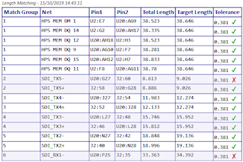
The Project Notes module in Proteus is home to a number of different report types, including a length match report and a differential pairs report. The length match report produces a data table which groups routes by match group and then lists out the total lengths versus target length for each route. A compliance check with the tolerances is included so that users can quickly spot problem routes.
The differential pair report also produces a data table with detailed information on the routed pair along with a compliance status column against specified parameters. It checks for total length compliance as well as both maximum and total length out of phase and unpaired distance.
As with all reports in Proteus, both of the data tables can be inserted into any other report directly from the toolbar in Project Notes. This makes it easy for users to create custom reports and include relevant data.