Advanced Simulation Features
The Advanced Simulation option can be added to all Proteus PCB Design and Proteus VSM products including the Starter Kit. It extends the functionality of the basic simulator to provide a full range of graph-based analyses.
Graph based simulation is akin to conventional SPICE simulation where you first draw the circuit, set-up source generators, select points to be monitored and then run the simulator. Trace results appear live as the simulation progresses with the full data set available for analysis when the simulation is complete. The Proteus Design Suite with the Advanced Simulation Features module makes this as effortless as possible.
What do you get?
The Advanced Features module helps with signal creation by including an HDL generator type. This provides access to a simplified HDL language called EasyHDL (a BASIC like language) which can be used to define arbitrary signals in HDL script. It also provides a dozen additional graph based analyses:
How does it work ?
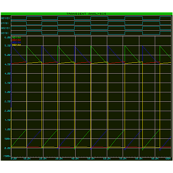
Having drawn the schematic, you choose the type of circuit analysis you require (transient, frequency, noise, etc.) by placing a Graph of the appropriate type on the schematic. You can place as many graphs as you want and can even have several graphs of the same type if you wish.
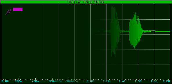
Next, drag and drop Generators to stimulate the circuit and Probes at points to be monitored. Analogue generators available include DC, Sine, Pulse, Piecewise Linear, File, Audio, Exponent and Single Frequency FM types and digital generators available include Edge, Pulse, Clock and Pattern types. For even more control you can define your input signal in script using an EasyHDL generator.
Finally you drag-and-drop one or more generators or probes on to a graph to choose what traces are displayed. A graph of a particular type with a given set of probes and generators is sufficient to tell ProSPICE what part of the circuit to simulate, and what type of analysis to perform.
Simulation results are shown live on the graph as the simulation progresses and then post simulation you can maximise any graph, zoom in or out on the data as well as use cursors to take timing, voltage and other measurements.
EDAi Simulation Insight
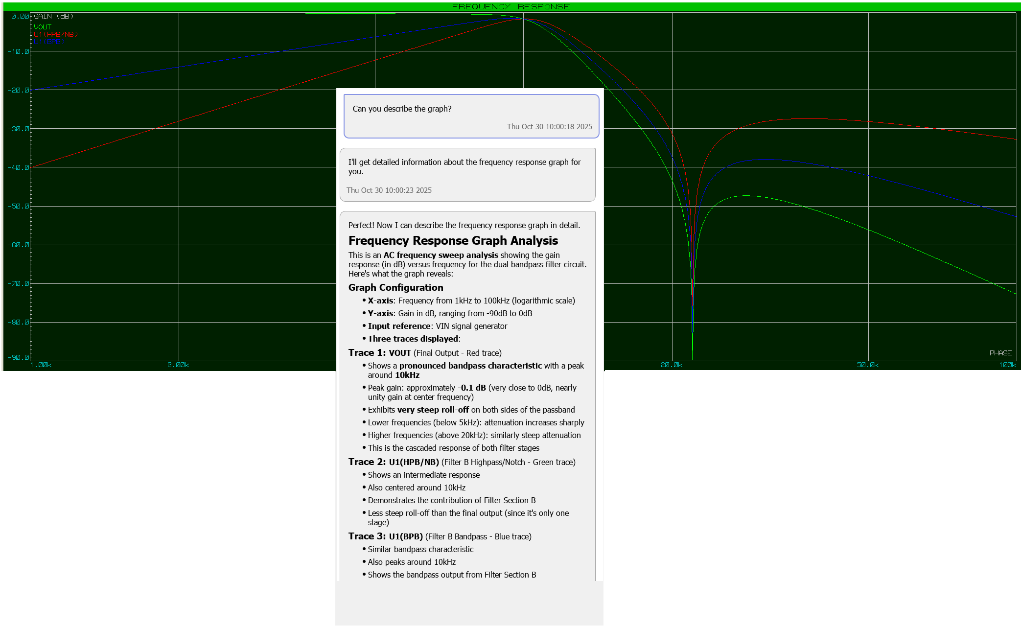
EDAi extends Advanced Simulation by helping engineers interpret what the results actually mean for circuit behaviour. Instead of leaving you to manually compare traces or search for relevant measurement points, the assistant can describe trends, extract key values, and relate the observed output directly to the circuit under test. For example, it can identify the −3 dB cutoff frequency from a filter response plot, or quantify ripple on a power rail as a percentage of the DC output. This transforms simulation results from raw data into engineering conclusions.
Because EDAi sees both the schematic and the graph data, it can connect behaviour with the components responsible for it. It can also reason across multiple plots — such as integrating noise spectral density to report RMS noise, or analysing overshoot and successive peaks to infer damping ratio and stability margin in a control loop. The process remains engineer-directed, but insight becomes faster and more targeted. By combining numerical results with contextual explanation, EDAi turns simulation into a guided analysis process rather than a manual measurement exercise.
Conformance Analysis
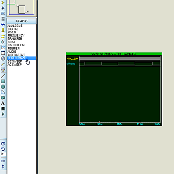
A conformance analysis is a unique quality assurance tool which compares one set of digital simulation results against another. The idea is that a design that has been previously accepted as working can be quickly re-tested after modification in order to prove that there have been no unwanted side effects arising from the change. This is particularly relevant in micro-controller based applications where the entire firmware program may need to be re-tested after changes have been made to the source code.
Conformance or non-conformance is determined by comparing the test and reference results at each edge of the first trace on the graph. Very significantly, there is no requirement for the edges in the test and reference copies of this control trace to occur at the same times. This means that changes in the absolute timing of events within the results data do not necessarily imply non-conformance. This is particularly relevant in micro-controller applications where any changes to the code will be bound to effect the absolute timing of events within the system. In such cases, the control trace may be generated by the code itself on entry and/or exit to the routines under test.