Introduction
Electronic signals can be either analogue or digital.
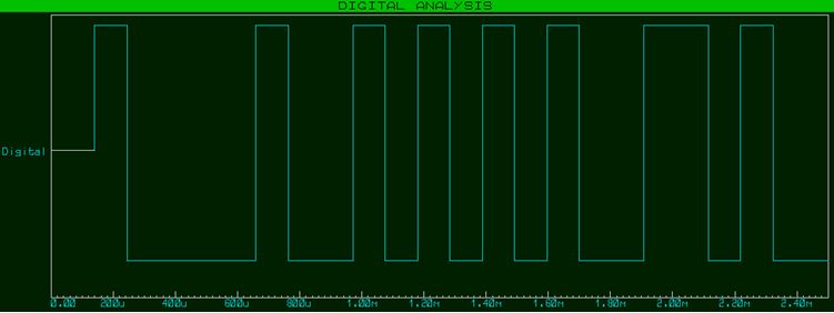
Digital Signals
We'll look at digital signals first.
Digital signals can only be in one of two possible states – on or off (high or low, true or false). They are binary and represent the way that modern computers work inside.
- Off (low/false) is typically represented by a voltage of 0V.
- On (high/true) is typically represented by a positive voltage, the magnitude of which depends on the particular system / protocol; 5V was traditionally the voltage used in most digital systems, however 3.3V has become more popular for newer systems. Some systems use lower voltages of 1.8V, 1.5V, 1.35V, 1.2V, etc – lower voltages use less power and so are more energy-efficient, however they are more susceptible to interference and attenuation, and so require more attention to hardware design.
Of course, the voltages in the system are unlikely to be exactly 0V and 5V, so there is some tolerance regarding what range of voltages represents on/high, and what range of voltages represents off/ low. Modern integrated circuits can consist of billions of tiny transistors, and the on /off thresholds depend on the type of transistors used:
TTL (Transistor to Transistor Logic)
Systems built with the older TTL (Transistor to Transistor Logic) technology (which uses BJTs – Bi-Polar Junction Transistors) accept anything from 2V and upwards (up to the maximum system signalling voltage) as on / high, and anything below 0.8V as off / low.
Meanwhile, on the output side, on should be at least 2.7V, and off should not be more than 0.5V. Voltages between 0.8V and 2V are undefined and could be interpreted as either on or off (apparently randomly).
CMOS (Complementary Metal-Oxide Semiconductor)
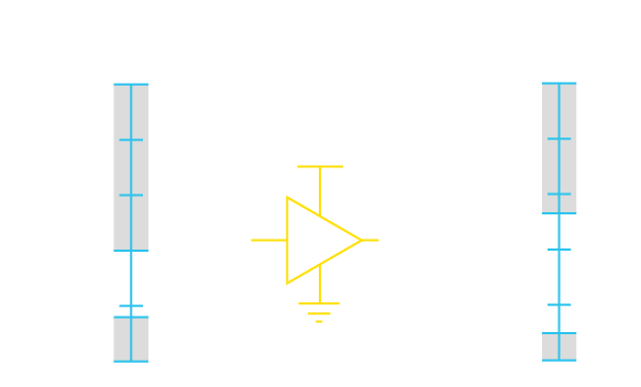
Systems built with the newer CMOS (Complimentary Metal-Oxide Semiconductor) technology (which uses MOSFETs – Metal-Oxide-Semiconductor Field-Effect Transistors) accept anything above about 2/3 (67%) of the operating voltage as on / high, and anything below approximately 1/3 (33%) of the operating voltage as off / low. For example:
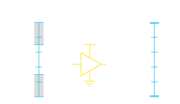
Or:
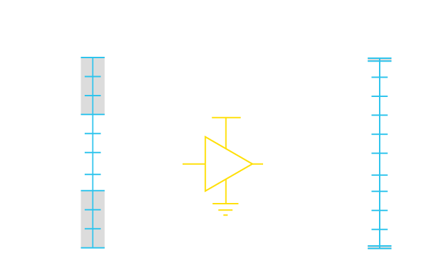
Outputs are expected to be very close to the logic power-supply levels. Inputs between the high and low thresholds are again undefined (and could result in a lot of power being drawn).
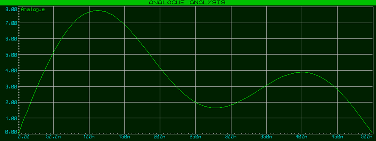
Analogue Signals
Whereas digital signals can only be at one of two possible levels, analogue signals can have an almost infinite range of values (limited only by the precision of the measuring equipment, and if you were to get atomically precise then technically the electrical charge of one proton or electron).
Analogue vs Digital
If analogue signals can have an almost infinite range of values, and digital signals only two possible values, then it probably sounds like analogue is better and the way-to-go? There are however drawbacks to analogue signals, which have resulted in most of our modern electronic systems being digital.
One drawback of analogue signals is that they are very susceptible to transmission errors; meaning that the the analogue signal arriving at the receiver is fairly guaranteed to not be exactly the same as the analogue signal emitted by the transmitter. This can be due to noise which is added to the signal during transmission (such as from electro-magnetic interference), as well as modification of the signal in the transmission process; a signal transmitted along a metal wire, for example, will be degraded/attenuated by the resistance of the wire. Digital signals on the other hand can be transmitted and copied exactly, so that the digital information arriving at the receiver is exactly the same as the digital information emitted by the transmitter.
Some examples of analogue signals could be the output voltage from a sensor or potentiometer. Microphones, for example, convert sound into analogue signals (voltage levels). LP records – the ubiquitous means of sharing music in times-gone-by – store audio in an analogue way (and are sometimes still prized for the infinite resolution they offer – more discussion on resolution follows below).
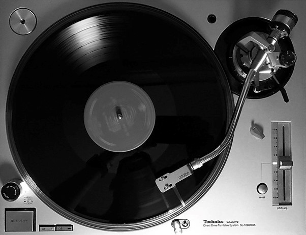 LP Record and Player
 Close up of LP Record Grooves
Converting Between Analogue and Digital
Conversion from Analogue to Digital is done with an Analogue to Digital Converter (ADC). Conversion from Digital to Analogue is done with a Digital to Analogue Converter (DAC).
When a signal is converted from Analogue to Digital, then a certain resolution must be chosen for the conversion. The analogue voltage is converted into a digital number, and the resolution determines the possible range of values for that number.
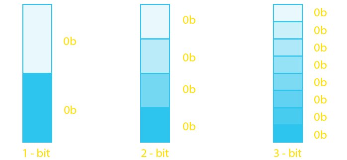
- A 1-bit ADC, for example, would have an output of only two possible values – either 0 or 1.
- A 2-bit ADC would have an output between 0 and 3.
- A 3-bit ADC would have an output between 0 and 7.
- Most popular microcontrollers have a 10-bit ADC peripheral built-in, which has an output of between 0 and 1023.
Now, the ADC has positive and negative reference voltages, which determine how the input voltage is scaled in the conversion. With a positive reference voltage of 5V and a negative reference voltage of 0V, for example:
- If the resolution 1-bit, then an output of 1 would mean an input of between 2.5V-5.0V, and an output of 0 would mean an input of between 0.0V-2.5V.
- If the resolution was 2-bits, then an output of 3 (binary 11) would mean an input of between 3.75V-5.0V, and output of 1 would mean an input of between 1.25V-2.5V, and an output of 0 would mean an input of between 0.0V-1.25V.
- If the resolution was 3-bits, then an output of 7 (binary 111) would mean an input of between 4.375V-5.0V, and output of 1 would mean an input of between 0.625V-1.25V, and an output of 0 would mean an input of between 0.0V-0.625V.
And so on. Note that the resolution corresponds to the possible number of binary digits in the output.
Depending on the particular ADC or microcontroller, it is sometimes also possible to supply separate reference voltages to the ADC (such as 1V for the negative reference and 2V for the positive reference), in which case the output will be scaled between those reference values.
Obviously higher resolutions seem better, however there is a price-performance trade-off here and the resolution is typically chosen depending on the application. Higher resolutions require more memory, more processing power, and more intricate ADCs; and are thus generally more expensive – and depending on the application, there will be a point where the practical returns on increasing resolution diminish, due to there being no further noticeable improvement in quality.
There are many different types of ADCs, such as Successive approximation and Sigma-delta; the details of which are beyond the scope of this particular article.
DACs do the opposite of ADCs and instead convert a digital number into an analogue voltage (again, obviously, with a certain resolution). There are also many different types of DACs, such as those based on resistor-ladders and those based on pulse-width modulation; the details of these are again beyond the scope of this particular article.
Signalling in a Proteus Simulation
Proteus is capable of mixed-mode simulation, meaning that it can efficiently simulate both analogue and digital signals with minimum processing power and maximum speed. Proteus includes simulation models for a wide range of ADCs and DACs, as well as a wide range of microcontrollers which have one or both of those converters built-in.
Head over to the sample designs page and take a look at ADC or DAC to quickly find a set of ready-made simulation sample projects that are included with the Proteus demo version.
All content Copyright Labcenter Electronics Ltd. 2026. Please acknowledge Labcenter copyright on any translation and provide a link to the source content on www.labcenter.com with any usage.Get our articles in your inbox
Never miss a blog article with our mailchimp emails
Advanced Simulation
Learn more about our built in graphing and advanced simulation features. Harness the mixed-mode simulation engine in Proteus to quickly test your analogue or digital circuitry directly on the schematic.
 Ask An Expert
Have a Question? Ask one of Labcenters' expert technical team directly.