This article follows on from our Passive Filters and Practical Opamps articles.
Introduction
Active filters introduce active elements into the filter circuitry; active elements being components which are separately powered by an external supply, rather than by the signal itself. By adding a buffer opamp after the filter, we can drive higher loads with the signal without attenuation; such as in the below high-pass filter example:
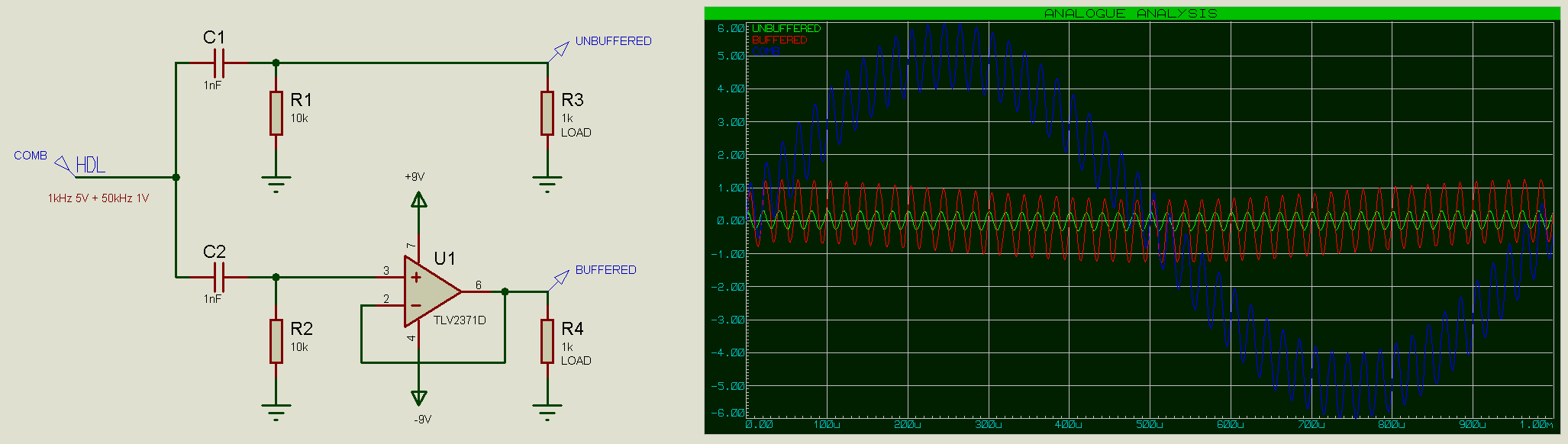
Note how the unbuffered output (green trace) is significantly attenuated compared to the buffered output (red trace).
Why use Active Components?
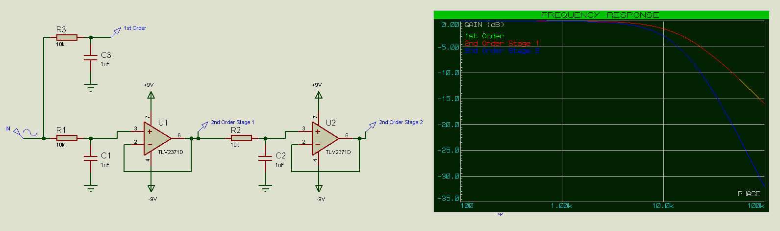
Adding buffers in higher-order filter chains also reduces attenuation between each link in the chain, and prevents filter elements in the chain from distorting the filter characteristics of other filter elements in the chain. If we look at the below 2nd-order low-pass filter for example, then we can see that the resistive element seen by the 2nd filter is not just R2=10k but rather R1 + R2 = 20k, and the capacitance seen by the 1st filter is not just that of C1 but the capacitance of C2 needs to be taken into account as well.
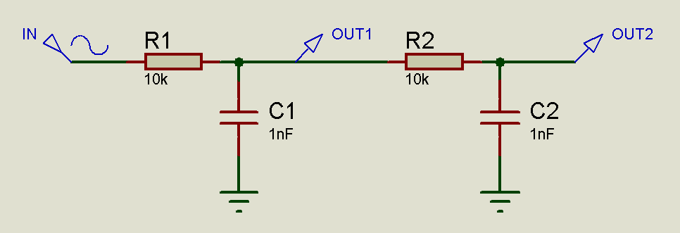
Given that
Cutoff Frequency = 1/2πRC
this has the effect of decreasing the cutoff frequency of the filter.
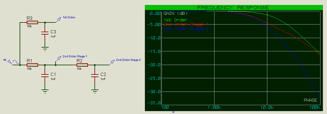
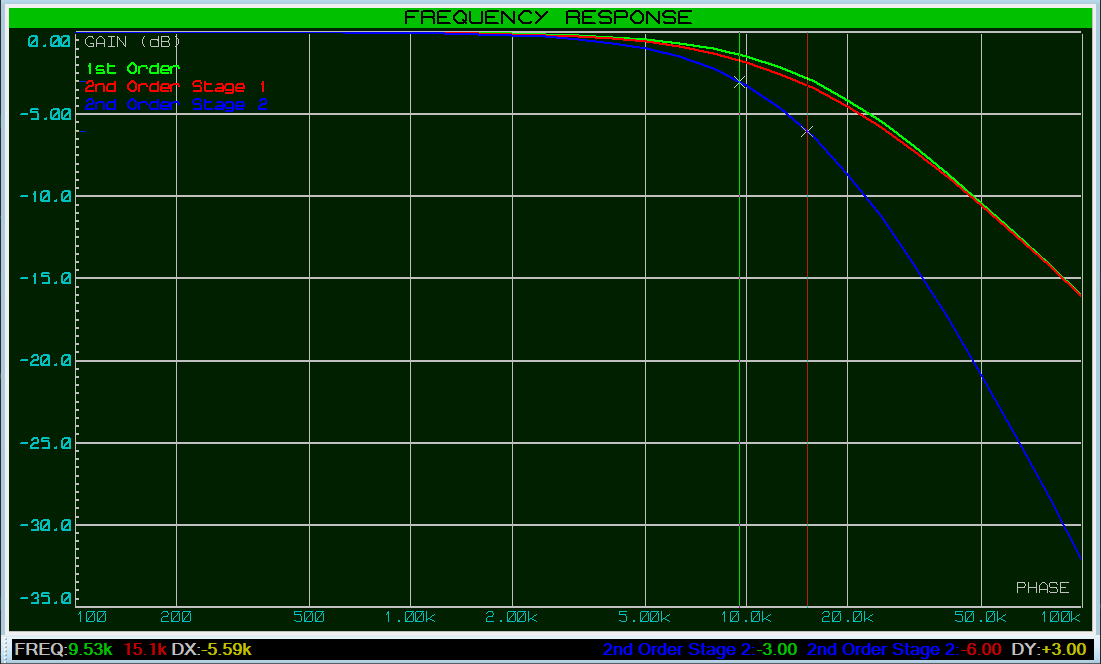
For R and C values of 10k and 1nF, we would expect a cutoff frequency (-3dB on the 1st filter stage, -6dB on the 2nd filter stage) of 15.9kHz, however we are seeing that it is somewhat lower than that. Note how the frequency response of the 2nd order stage 1 initially follows that of the 2nd order stage 2, because at low frequencies the capacitors act as open circuits (as if they’re not there), however at higher frequencies the frequency response of the 2nd order stage 1 then follows that of a 1st order filter as C1 starts to act as a short-circuit with a low resistance compared to that of R2.
This is more pronounced if we decrease the resistance and increase the capacitance (maintaining the same RC constant however) in the filter 2nd stage:
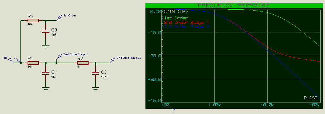
This shifts the cutoff frequency even lower.
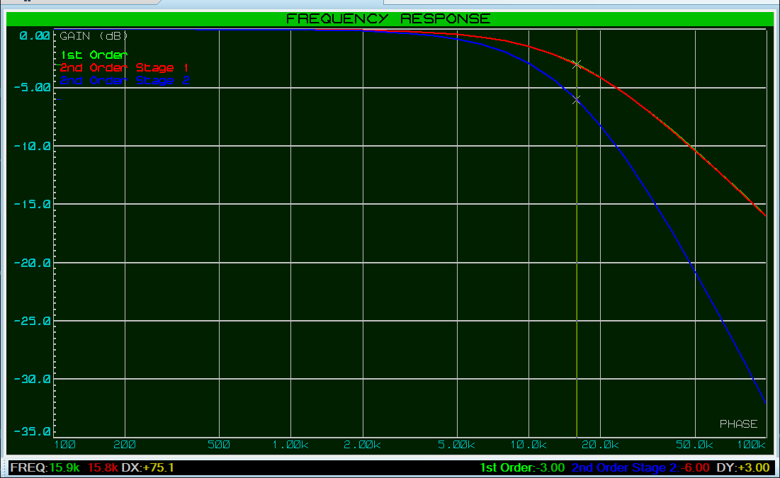
A way in which this can be mitigated is to have the input impedance of the 2nd stage be at least an order of magnitude (10x) greater than the output impedance of the 1st stage – i.e. make R2 10x larger than R1 (and C2 10x smaller, which maintains the RC constant).
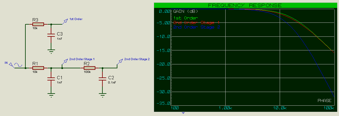
Now we can see that the frequency response of Stage 1 of the 2nd order filter closely matches that of the 1st order filter. The cutoff frequency is also much closer to the expected 15.9kHz.
Further decreasing the output impedance of the 1st stage and/or increasing the output impedance of the 2nd stage would continue to bring the cutoff frequency closer to that expected; it would never quite get there exactly however, and adding a 3rd (or 4th, etc) filter stage would further complicate the situation.
And (finally!) this is why we introduce active components.
In this case we can see that Stage 1 of the 2nd order filter exactly matches that of the 1st order filter, and the cutoff frequency is 15.9kHz as expected.
We can easily add additional filter stages as needed to get the desired sharpness of roll-off.
Note that the attenuation in dB at the cutoff frequency increases by -3dB for each additional filter stage added. A 1st order filter will have an attenuation of -3dB at the cutoff frequency, a 2nd order filter -6dB and a 3rd order filter -9dB, etc.
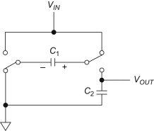
Sallen-Key Topology
The Sallen-Key topology is a popular 2nd order filter topology which uses a single opamp (instead of 2 as we’ve just done above).

The Z elements are chosen depending on whether a low-pass, high-pass, band-pass or band-stop filter is required.
 Low-Pass Sallen-Key Filter
 High-Pass Sallen-Key Filter
Gain can also optionally be added (using a voltage divider on the inverting input of the opamp):
 Sallen-Key Filter with Gain
The interesting feature of the Sallen-Key filter is that the first stage is connected not to ground, but rather to the output of the opamp. This adds a feedback from the output of the opamp back to the positive input, which can be used to increase the “Q” of the filter.
The Quality Factor, Q
In science, the Quality Factor or Q of an oscillating system describes how dampened it is (or technically rather how underdamped it is – the opposite of dampened). A pendulum swinging in the air will have a higher Q factor than a pendulum swinging in water; the pendulum swinging in the air will lose less energy to resistance on each swing and therefore swing for longer.

- Q = 1 means that there is no damping / underdamping, and the amplitude of the signal stays exactly the same.
- Q > 1 means that the signal gets amplified (increasing).
- Q < 1 means that the signal gets attenuated (decreasing).
In terms of filter response, the Q of the filter describes how it behaves around the cutoff frequency (10kHz in the graph below):
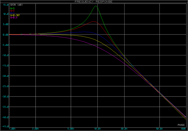
- Q > 1 will amplify the signal at the cutoff frequency.
- Q = 1 will keep the signal amplitude the same at the cutoff frequency.
- Q < 1 will attenuate the signal at the cutoff frequency.
Note also that higher Q values have sharper corners at the cutoff frequency. A passive 1st order filter will have a Q of 0.707 (-3dB), and a passive 2nd order filter will have a Q of 0.5 (-6dB). Using the Sallen-Key active filter topology however, we can choose the value of Q for our application – we may prefer a Q of 1 for example, giving us a filter which keeps the signal unattenuated closer to the cutoff frequency and then with sharper roll-off at the cutoff frequency.
The way this works is that the filtered signal from the output is fed back in to the input signal, resonating with it around the cutoff frequency and thus increasing its amplitude (and thus Q).
Low Pass Calculations
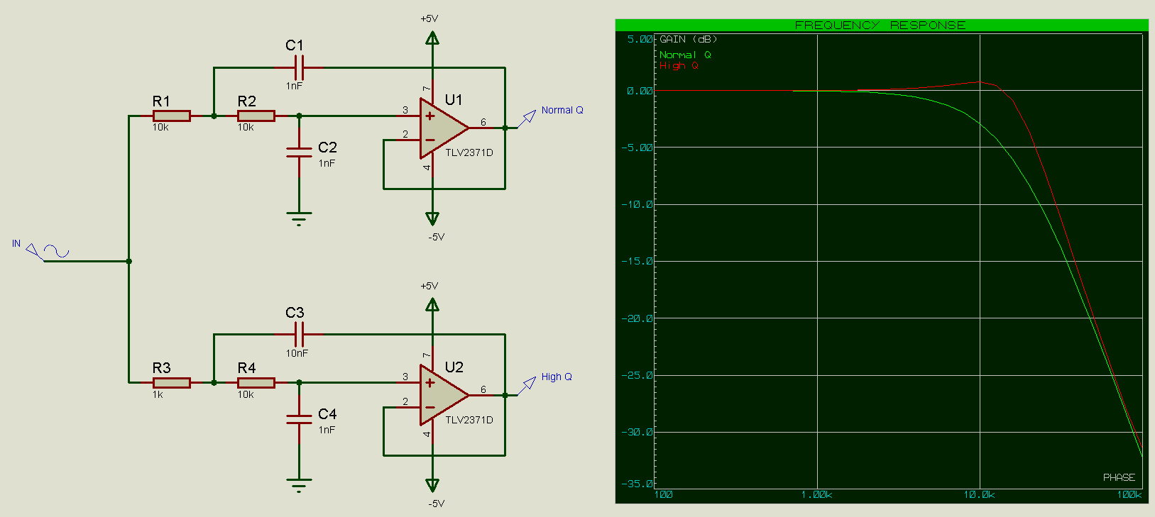
The mathematics behind Sallen-Key filters is complex, and an in-depth analysis is beyond the scope of this particular article. There are online and offline calculators available which can conveniently calculate the R and C values for a given cutoff frequency, Q and gain. We will however look briefly at one of the simplified cases, where the gain is 1 (unity) and the resistors and capacitors are set as ratios of each other (which is similar to how we have created higher order filters so far).
Low Pass Sallen Key
Let R2 = xR1, and C2=(1/x)C1.
This is similar to what we have done previously (when we created a 2 stage passive filter which mitigated the effect to the cutoff frequency), and the formula for the cutoff frequency is still 1 / 2πRC.
The formula for Q is then x / (x + 1).
From this we can see that if x=1 (component values in both stages the same) then we get a Q of 1 / (1 + 1) = 1/2 = 0.5; this is the same Q which we would have gotten with a usual 2 stage filter (-6dB). If we increase x to 10 however then we get a Q of 10/11 = 0.91, which is much higher than what we have had previously.
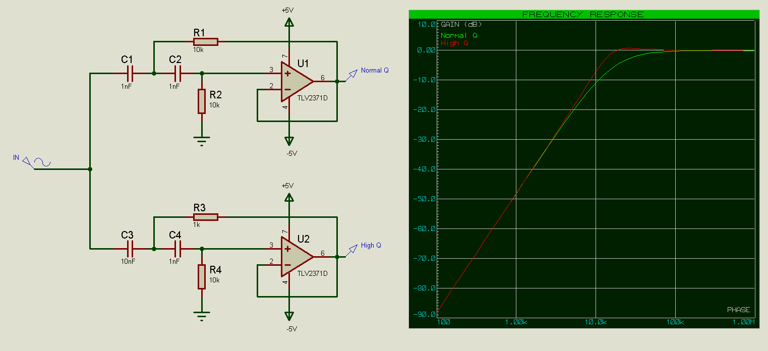
High Pass Calculations
The calculations here are all the same, so again let R2 = xR1, and C2=(1/x)C1.
High Pass Sallen Key
For x = 1 we again have Q = 0.5, and for x = 10 we again have Q = 0.91.
Download all the Proteus schematic files used in this article in a single zip file here.
A demo copy of Proteus is required to open the .pdsprj file.
Get our articles in your inbox
Never miss a blog article with our mailchimp emails
Advanced Simulation
Learn more about our built in graphing and advanced simulation features. Harness the mixed-mode simulation engine in Proteus to quickly test your analogue or digital circuitry directly on the schematic.
 Ask An Expert
Have a Question? Ask one of Labcenters' expert technical team directly.