The Fourier Transform
Did you know that almost anything can be decomposed into a combination of frequencies (sinusoidal waves)? Take this drawing of Homer Simpson for example:
Given enough frequencies combined together (represented in this case by a combination of rotating circles), the drawing can be completed to a high accuracy. An interactive version of the experiment, where the number of frequencies can be varied, is available here.
How exactly do you go about figuring out which frequencies (including their phase and amplitude) are needed to create the drawing though? The answer is some mathematical brilliance known as the Fourier Transform. The Fourier Transform can take any complex signal and decompose it into individual frequencies
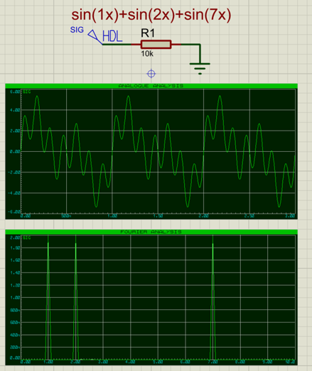
The above screenshot shows:
- A signal being generated in Proteus using a scriptable generator
- An analogue plot of that signal
- A Fourier Transform of that signal decomposing it back into its constituent frequencies.
Below is a picture of a Digital Spectrum Analyser, which can be used for example in the analysis of radio frequencies:
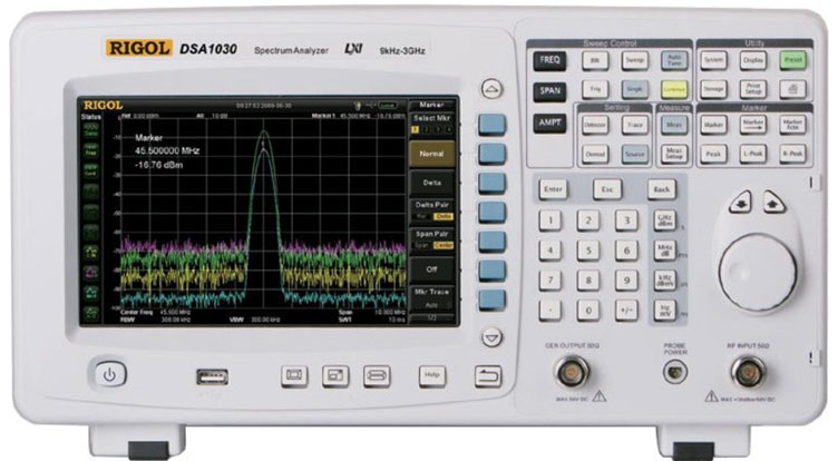
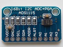
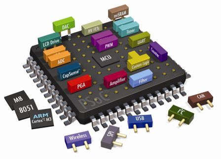
Modern microcontrollers, which feature Digital Signal Processing (DSP) instructions, can use Fast Fourier Transforms to analyse an analogue signal (digitised through an Analogue-to-Digital-Converter – an ADC) and detect and/or filter certain frequencies for example. The advantage over traditional analogue filters, is that the behaviour can be changed with software on-the-fly rather than by having to change physical hardware components.
The Fast Fourier Transform
Mathematically, the Fourier Transform computes exactly the transform of a function from the Time Domain to the Frequency Domain. In practice however, for an electronic engineer processing a Fourier Transform on a digital microcontroller, we can only process a signal at a given resolution. If this signal is being read in through the ADC (Analogue-to-Digital Converter), then this can also only be done at a given rate/resolution.
The Fast Fourier Transform (FFT) is an efficient method of computing a Fourier Transform on a sampled signal. When designing a system involving an FFT, there are a couple of decisions which need to be made:
- The Sampling Frequency
- Number of Samples / Sampling Duration
Sampling Frequency
The sampling frequency, meaning how quickly / how often the signal is sampled (i.e. read through the ADC), will determine the maximum frequency which the FFT can detect. The reason for this is a problem known as aliasing. Take the following two signals for example (Yellow and Blue):
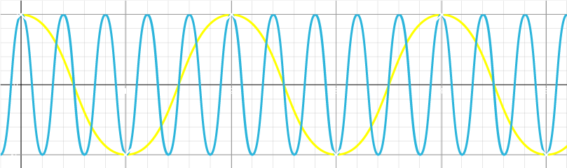
If the Yellow signal, at a frequency of 2.5Hz, is sampled at a frequency of 1Hz as indicated by the white x’s, then it will produce exactly the same data as sampling the Blue signal at 0.5Hz. The frequency at which aliasing will begin to occur is called the Nyquist Frequency, and is equal to the sampling frequency divided by 2; so for the above example (sampling at 1Hz), any signals with a frequency of 0.5Hz or higher may become aliased to a lower frequency during in an FFT. Even the 0.5Hz Blue signal, which is equal to the Nyquist Frequency in this case, could become aliased to zero if sampled at the wrong time
For this reason, it is important to set the sampling rate high enough to accommodate the maximum frequency to be detected / expected to be received into the system, and to cut off any higher frequencies with an analogue low-pass filter if necessary.
Number of Samples
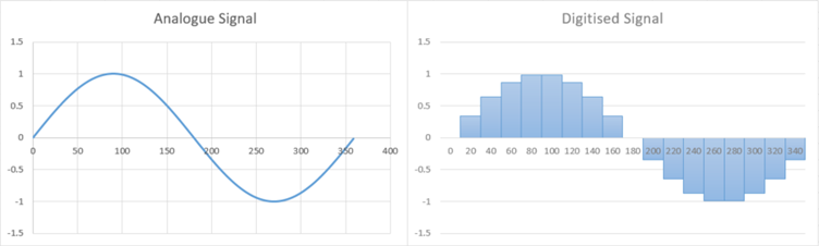
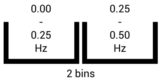
The second consideration, being the number of samples to be taken, will determine the resolution of the FFT. The FFT does not in fact tell us exactly which frequencies are present in the signal, but rather which frequencies are present within given frequency ranges. If we take only 2 samples at 1Hz for example, then the FFT can only tell us the combined strength of signals in the 0.00Hz<->0.25Hz range and the combined strength of signals in the 0.25Hz<->0.50Hz range. The number of results which the FFT produces, also known as output bins, is equal to the number of input samples.
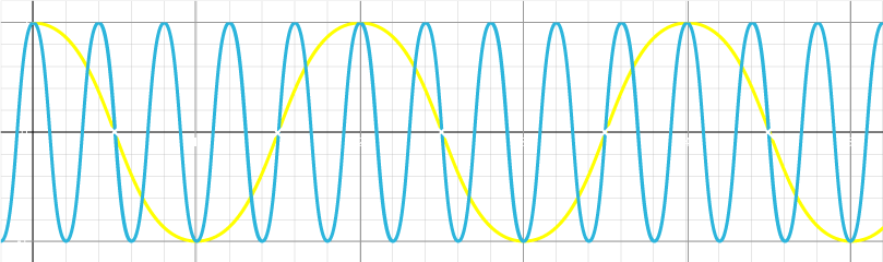
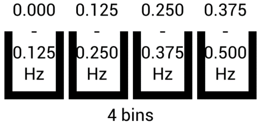
Increase the number of samples / bins to 4, and we double the resolution:
Of course the solution seems to be to take as many samples as possible, in order to get as high a resultant resolution as possible, however the drawback here is how quickly and how often we want results: if we take 10 samples at 1Hz then that will take 10s to complete acquisition – take 60 samples and it will take 60s. In applications where the system must react quickly to a detected frequency, or the frequency is only actually present in the signal for a relatively short period of time, then there are practical limitations to the number of samples which can be taken. Another limitation is how long it actually takes the microcontroller to compute the FFT, as an FFT on more samples will take longer to compute. The other solution is to take more samples more frequently – to sample faster and get more samples within the same time period – and this is a valid solution; the limitations being how fast the ADC of the microcontroller can sample and how quickly the microcontroller can compute the FFT.
It needs to be mentioned that, due to the nature of the FFT algorithm, the number of samples / bins should be a power of 2 for faster calculation – so sample sizes of 2, 4, 8, 16, 32, 64, etc are all good. Most FFT libraries will require the number of samples to be a power of 2.
The Goertzel
If all you need to do is try to detect the presence of one particular frequency in a signal, then the Goertzel algorithm is a faster way to do this. The concepts are the same in terms of the sampling frequency and the number of bins, however the Goertzel only calculates the value for one of the bins.
Conclusion
The Fourier Transform is a very interesting concept, and has extensive applications in engineering. Whilst we haven’t delved into the deep maths of exactly how the Fourier Transform works, we’ve looked at the practicalities of what it can do and how it is implemented in practice through the FFT.
Proteus includes a number of tools and sample designs for both your analogue and digital signal processing needs, including:
- Analog simulation, such as analog signal filters
- Analogue signal generation; using both scriptable and interactive generators.
- Analogue signal analysis; including Fourier Analysis and Frequency Analysis.
- DSP (Digital Signal Processor) Microcontroller simulation.
Get our articles in your inbox
Never miss a blog article with our mailchimp emails
Advanced Simulation
Learn more about our built in graphing and advanced simulation features. Harness the mixed-mode simulation engine in Proteus to quickly test your analog or digital circuitry directly on the schematic.
 Ask An Expert
Have a Question? Ask one of Labcenters' expert technical team directly.