Introduction
I2C (or IIC) stands for Inter-IC Communication and is one of the popular microcontroller communications protocols. I2C is typically used to communicate with sensors but finds uses in many other applications as well.
I2C is a synchronous protocol, meaning that it has a clock line (for more information on synchronous and asynchronous communication please see our article on the topic).
I2C Communication
Although I2C uses only two communications lines (clock and data), it can accommodate multiple devices on the same I2C bus; this is accomplished by making use of an addressing scheme where each device on the bus has a unique address. Communication starts with sending out the device address for which communication is intended, and the addressed device must then acknowledge that it is present and ready to communicate.
Since there is only one data line (SDA - Serial Data), used to both send and receive data (half-duplex), a scheme is needed whereby both the master and the slave device in the communication can control the data line without clashes. Bus contentions must be avoided, where one device is trying to write a high to the bus and another device is trying to write a low to the bus, which would create a short circuit.
In order to accomplish this, an open-drain scheme is used; where either device can only ever drive the bus ‘low’ or otherwise ‘release’ it, and pull-up resistors are used to pull the line high when it is released (if you are not familiar with the terms open-drain or pull-up resistor then please see our article on the topic). The clock line (SCL - Serial Clock) also makes use of this scheme, and some innovative techniques are used to add some useful features to the I2C protocol - more on that shortly.
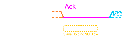
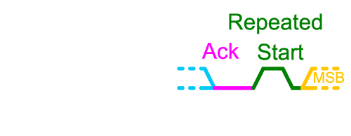
The diagram below illustrates the typical features of an I2C communication sequence:

Communication starts with the I2C bus idling - with both the clock and data lines undriven and therefore pulled high by the pull-up resistors. Communication is then initiated by the master (the device initiating communication) pulling first the SDA line and then the SCL line low - this is defined as a Start condition.
Next the master transmits the 7-bit address of the device it wishes to communicate with, followed by a ‘read or write’ bit which indicates whether the master wishes to write to (0) or read from (1) the device. The data line is considered valid (read from by the slaves) on the rising edges of the clock line, and data is transmitted Most Significant Bit (MSB) first (if you are not familiar with the terms least significant bit and most significant bit then you can read more in this article).
After the address has been transmitted, and assuming that the addressed slave is present on the I2C bus, the master will release the data line (open drain) and the slave will hold the data line low for one clock cycle in order to acknowledge (ack) that it is present and ready to communicate. If the slave is not present on the bus then the pull-up resistor will pull the data line high, and the master will know that the slave is not available.
At this stage, data can be transmitted between the Master and the Slave. If data is being read then the slave will transmit the data (whilst the master continues to drive the clock line), or if data is being written then the master will transmit the data. After each data byte there is a single Ack bit, during which the receiver (could be the master or the slave, depending on which side transmitted the data) should hold the data line low in order to indicate that it has received the communication (and is ready to proceed with the next communication if applicable).
Clock Stretching
Slave devices on the I2C bus have the ability to delay their responses (if they are still busy and not yet ready to respond) by holding the clock (SCL) line low, a feature known as ‘clock stretching’; once ready to respond then the slave releases the clock line and data transmission continues. This is similar to the flow control lines in UART (CTS/RTS), but without requiring additional communications lines (note that the SPI protocol has no flow control feature).
One or more data bytes may be communicated in sequence, with an ack occurring after each byte.

Repeated Start
Because slave devices may have a multitude of values available to be read (such as multiple sensor reading values, as well as settings values), the slave may require that the master first write an instruction indicating what it would like to read before proceeding with the actual reading. In this case the master will first issue a write with the data being the instruction indicating what should be read, and then the master will issue read immediately after that. In between however there is no stop issued, but rather the master uses a repeated start condition (followed by the 7-bit address and 1-bit read/write bit, obviously now set to read) to make the switch from writing to reading. To issue a repeated start, the master first takes the data line high, then the clock line, and then the master takes the data line low followed by the clock line.
Data Rates and Distances
Communication on the I2C bus usually takes place at either 100kHz or 400kHz. These relatively low speeds are fine for small amounts of data transmission, but SPI (using clocks in the MHz range, and possibly in Dual or Quad mode) is usually preferred for high throughput applications where large volumes of data need to be transmitted. I2C is usually only used for relatively short distance communication, however schemes exist where I2C can be transmitted over differential pairs to communicate over longer distances (please see our article on high-speed design for more information on differential pairs).
Proteus includes a dual mode (master or slave) I2C Protocol Analyser instrument that you place and wire on the schematic. It then allows you to type and inject I2C sequences into the running simulation and view received packets from other devices on the I2C bus. This is an excellent teaching tool and allows for quick and easy testing of both master mode and slave mode firmware. You'll find a lot of sample designs include I2C communications with sensors or multi processor projects. These can all be simulated in the demo version
All content Copyright Labcenter Electronics Ltd. 2026. Please acknowledge Labcenter copyright on any translation and provide a link to the source content on www.labcenter.com with any usage.Get our articles in your inbox
Never miss a blog article with our mailchimp emails
Advanced Simulation
Learn more about our built in graphing and advanced simulation features. Harness the mixed-mode simulation engine in Proteus to quickly test your analogue or digital circuitry directly on the schematic.
 Ask An Expert
Have a Question? Ask one of Labcenters' expert technical team directly.