There's no doubt that PCB design is becoming ever more complex with component footprints getting smaller and space on the board at a premium. A comprehensive design rule system is essential to impose order on the PCB and ensure suitable clearances between conductors. Proteus includes a hierarchical design rule system that is simple to use and flexible enough to cope with almost any user requirement.
- Set design rules on a PCB layer or an electrical net class.
- Place user defined rooms on the PCB and set rules to apply inside them.
- When problems occur view violation areas at a mouse click.
- Generate a design rule report and Pre-Production Checklist.
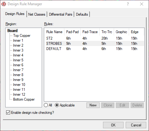
Basic Design Rules
The simplest design rule is a set of clearances that applies to the entire PCB and dictates how close objects of various types (pads, tracks, etc.) can get to each other. This rule can then be overriden by a more specific rule of onoe of two types:
1)Electrical Scope: Here the clearances apply only to signals of a particular net class (e.g. Power).
2)Physical Scope. Here the clearances apply only on a layer or in a particular area.
The hierarchy of design rules is covered in more detail in a blog post on the subject.
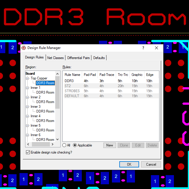
Design Rule Rooms
Design Rule Rooms are areas of the PCB defined by the user in which specific clearances apply. A dedicated room placement mode is used to drag out and position a box on the PCB and then the required layer set is specified. Finally a design rule is created that applies to the room and the required clearances are entered.
These rooms are a really useful tool in setting design constraints in all sorts of places. For example, around the fanout areas of BGA's or around high voltage circuitry near the supply.
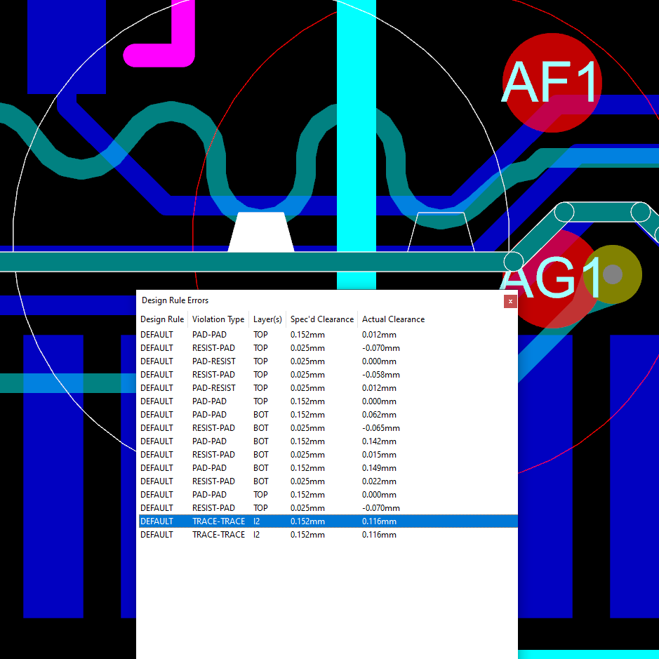
Live DRC
Once all of your design rules have been set up the system will honour the clearances during operations like routing and power plane placement. However, Proteus also includes a live design rule checker which will flag errors if objects become too close together during user editing.
When the list of errors is opened it shows the design rule being violated along with the expected and actual clearances. A double click on an entry will zoom the editing window to show the location of the error on the board. Also, the entire area of violation is highlighted making it much easier to see how to correct the error.
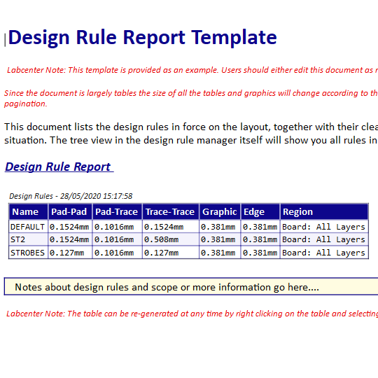
Reporting
In addition to the design rule system Proteus also includes a dedicated reporting module. Reports such as the single pin net report will list all pins not marked NC which are not connected. This, together with the NC terminals, provides an auditable way to verify that all connections are present and that all NC pins have received developer attention. The length matching and differential pair reports detail relevant high speed lines along with a pass/fail column showing at a glance if everything is inside specified tolerances.
Find out more on the reporting page.
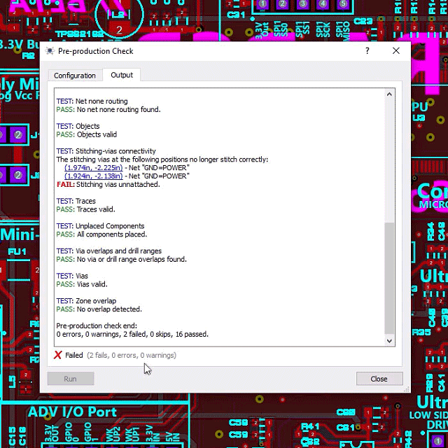
Pre-Production Checklist
The pre-production checklist is an automated series of checks that takes place before manufacturing output files are created. It first performs a series of simple tests on common errors such as not every component being placed or parts having duplicate ID's. Next, it performs a more detailed analysis on the board and will log things like stitching vias that no long connect two planes or incompatible drill ranges. Finally, it will re-generate and compare all copper pour through a completely separate code path to ensure validity.