Making sure that there are safe clearances between objects on the PCB is a top priority. Modern electronic products are more complex than ever before, operating at higher speeds and needing to fit into smaller enclosures; this means we need more control over electrical clearances during board layout. Fortunately, the EDA industry has a well established and fairly standardized system for specifying electrical design rules, allowing us to limit a rule to a physical area of the PCB and/or to a certain number of signals.
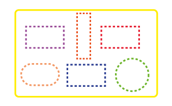
Physical Scope
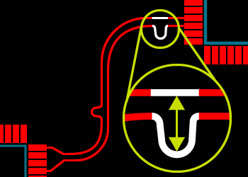
Physical scope starts of course with the entire PCB. There is always a board rule, sometimes called the default rule. This rule applies everywhere on the board that is not overridden by another rule. At its simplest level we define a distance between pads, between a track and a pad and between two tracks. The EDA tool will then monitor the distances between objects as the PCB is placed and routed and will warn us if objects violate the specified clearances.
It’s very common however to want different clearances between objects in different parts of the PCB. For example, we may allow the space between tracks on inner layers to be smaller because they are better protected from things like dust and condensation. To do this a layer rule would be created with different clearances which would override the board rule on the specified layer.
Another common requirement is for tight clearances on several layers in the area inside and around a fine pitch SMD or BGA to enable all of the signals to fanout and escape onto the board. This type of rule is called a region rule or a room rule and may be handled differently by different EDA tools. In Proteus, the room tool is used to draw out the area, specify which layers it applies to and give it a name. Then a rule is created that applies to that named area and the necessary clearances are defined.
Electrical Scope
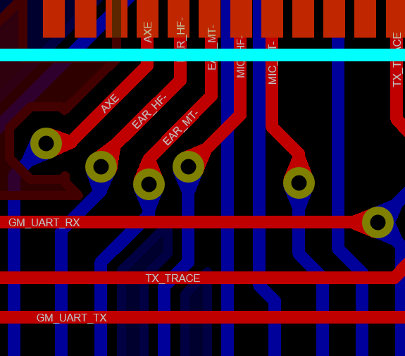
Sometimes the requirement is to apply clearances to types of signal rather than to physical areas. For example, more space may be required around power tracks than low current signal tracks. This is where net classes and electrical scope becomes useful. A net class is just a user named set of signals that will have common properties on the layout. These properties include things like track width, via style used and of course clearances. Once the net class is created, the user simply adds a design rule that applies to the named net class and specifies the required clearances.
It is even possible to create more granular electrical rules. For example, you can set up a rule which applies to a net class only with respect to other objects on the same net class. This would let you define specific clearances between two tracks on the same net class such as a differential pair.
Priority Levels
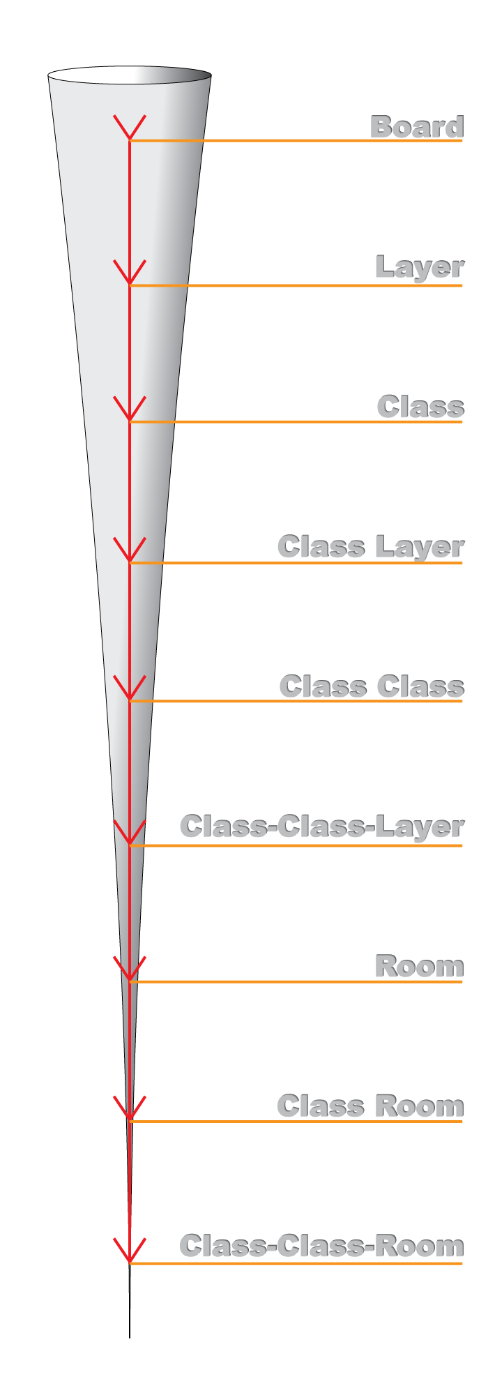
Given all these possibilities, how do we know which rule applies between two objects? Different EDA tools work in different ways of course, but the priority levels of rules are pretty standard across the industry.
At the top level we have the board rule or default rule. This will apply everywhere if no other rules are added. After that, the priority of rules in physical scope is fairly obvious with a layer rule overriding the board rule on its designated layer and a room rule taking precedence over both in the area of the board it applies to. The smaller the physical scope the higher the priority.
Interspersed with these are rules that also have an electrical scope (class rules). These take priority over standard rules with the same physical scope. Those rules that target only one net class with respect to another (class class rules) are the highest priority inside a given physical scope.
The basic principle is that the narrower the set of objects the rule applies to, the higher the priority of the rule.
The other important thing to remember is that a room rule wipes out all other rules that might affect the area of the room. It’s easiest therefore to think of a room as a mini-board and start again with design rules inside the room.
This all sounds very complicated but after a little while in use you’ll find it does actually make sense. Also, the chances are good that you won’t need to use all of the different priority levels but it’s useful to know that the flexibility is there if you need it.
If you’d like to learn more about how to set up and work with design rules in the Proteus Design Suite watch this video:
All content Copyright Labcenter Electronics Ltd. 2026. Please acknowledge Labcenter copyright on any translation and provide a link to the source content on www.labcenter.com with any usage.Get our articles in your inbox
Never miss a blog article with our mailchimp emails