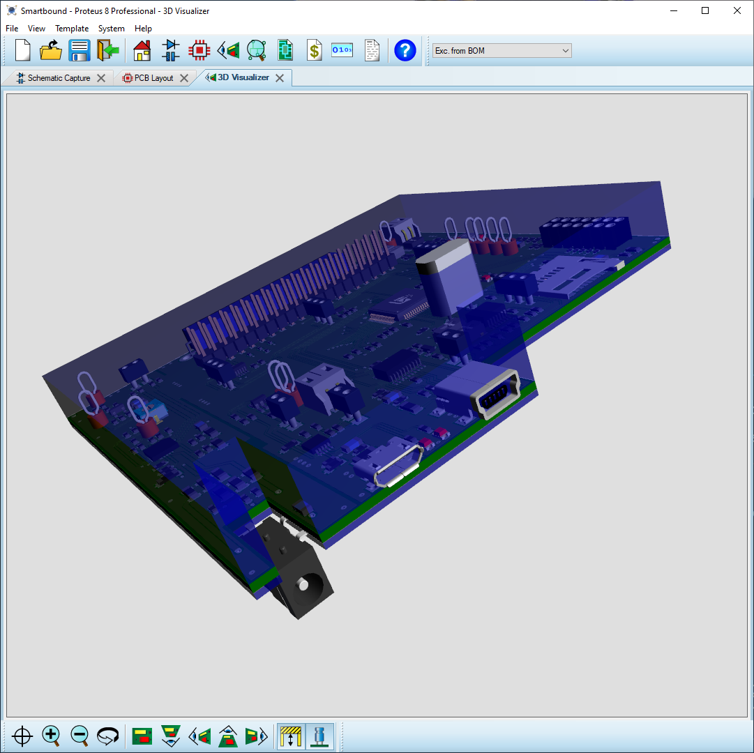
The 3D viewer transforms your 2D Layout into 3D, including board thickness, component models and render of silkscreen, solder and tracks/vias. Components are populated according to the fitted status when working with assembly variants providing an accurate visual of the assembled product in each case.
Several preset views of the board are provided along with a flip command and both zoom and 'fly-by' navigation is implemented with the mouse.
- 3D view of the PCB with preset views and fly-by navigation.
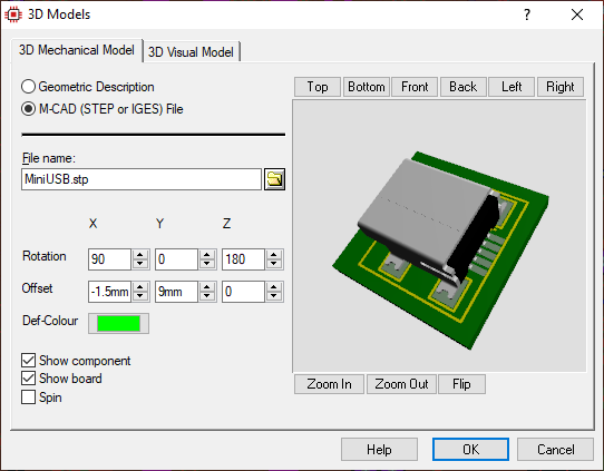
- Easily import STEP/IGES component models.
- Bareboard view provides an additional PCB analysis tool.
- Export STEP/IGES for use in your MCAD tool of choice.

Tools
The 3D Viewer includes a bareboard mode which removes all of the components models from the PCB. This is extremely useful for analysis as it makes it easier to spot badly positioned silkscreen or testpoints and gives better sight of the soldermask profile.
The height plane tool adds a semi-transparent 3D bounding box around the PCB making it easier to spot problem components in the product enclosure.

3D Models
Every footprint can be associated with a 3D STEP or IGES model. These are typically imported automatically via the integrated web import with no user action required. Otherwise, 3D models can be sourced from any 3D modelling website and easily associated with the footprint in Proteus.
In the unlikely event no STEP file exists the user can create a geometric model inside Proteus, using a simple scripting language to define things like pin types and extrusions. If no model is supplied at all for a part a default extrusion will be taken from the silkscreen outline and the component body coloured in bright red.

Output
Regardless of how the component models are created the entire populated board can be exported as a STEP assembly for use in MCAD tools like Solidworks ®. Both STEP AP203 and STEP AP214 as well as IGES and STL output are supported and the simpler wireframe IDF can be generated as well..