The junction temperature of a silicon device can be an important design consideration for linear regulators. Let's say that we want to verify the effects of a given heat sink and prove whether or not it is effective at keeping the regulator safe at ambient temperatures and in the rated conditions. This article explores how we can create a lumped element electrical model to represent the physical thermal system and then use this to help us choose/test an appropriate heat sink.
The Linear Regulator Circuit
For our example let's say we have designed a simple 5Vdc linear regulator as shown below and that we need a continuous output current of about 1A to the output load.
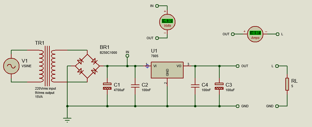 Simple Linear Regulator Circuit.
The regulator will have to reliably provide the required output current at the ambient temperature of 50°C maximum and, above all, the regulator will have to work safely for hours without getting fried.
A demo copy of Proteus is required to open the .pdsprj file.
Power Dissipation
Our first step is to figure out the power dissipated by the regulator U1. To do this we will measure the voltage across the regulator itself between the input and output pins and the output current in the Load. Proteus can help with this by using a DC Voltmeter and a DC Ammeter connected as shown in the picture above. This gives us 6.32Vdc and 0.97Adc in the load which, for an output of 5Vdc and 1A nominal, implies that U1 will dissipate a power of
P(W)=6,32V*0.97A=6.13W
From the datasheet we can get the maximum power dissipation at the needed ambient temperature. The curve is shown below:
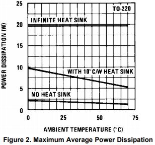 Power Dissipation Characteristics for LM7805.
At the maximum ambient temperature of 50°C we can see that average power that regulator can dissipate without a heat-sink is well below the expected projected value of 6.13W. This also implies that the junction temperature of the regulator will dangerously rise up and the regulator will likely be damaged. So, we need to provide a means to dissipate the temperature from the regulator by using a suitable heat-sink.
From the regulator datasheet (LM7805) we get the value of the junction to case thermal resistance (metal lead) for TO220 case and the maximum junction temperature as follows:
Rjc = 1.7°C/W Jtmax=150°C
The Physical Thermal Model
Let's now look at a physical thermal model of a generic device with heat-sink and identify all the thermal parameters.
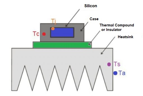 Generic Physical Thermal Model.
The formula we need is:
Tj = Pd (Rj-c + Rc-s + Rs-a) + Ta
Where:
- Rj-c is the junction-case
- Rc-s is the case-sink
- Rs-a is the sink-ambient resistances
- Pd is the dissipated power
- Ta is the maximum ambient temperature
- Tj is the junction temperature
Tj will be the junction temperature established from the thermal equilibrium due to heat transfers elements, ambient temperature value and dissipated power.
'Lumped Element' Thermal Model
What we now want to do is transpose this thermal model into an electrical model using Proteus. We will use a thermal RC model, also known as a 'lumped element' model
 Lumped Element Model.
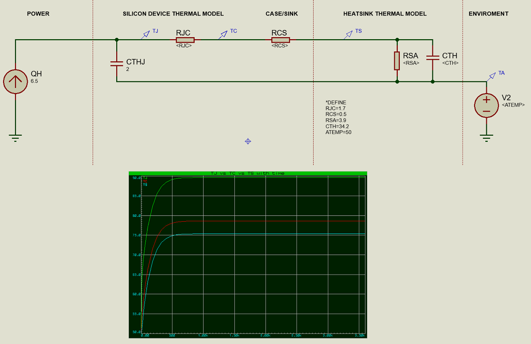
All thermal elements representing heat transfer resistances are simulated with electrical resistors. Also, the dissipated power is simulated with a current generator the which current is equal to Pd value and represents the heat flow. The ambient temperature is represented by a voltage generator and, finally, the capacitors represent the junction and heat-sink thermal capacities, CTHJ and CTH.
A useful technique in Proteus is to represent the values for each element of the model with generic variable names on the device. You'll see this in the screenshot above. We can then apply part specific values in a *DEFINE block when we calculate them for a particular heat sink.
A demo copy of Proteus is required to open the .pdsprj file.
Calculating Element Values
So, we know that our *DEFINE block in the thermal RC model defines all numerical values of the thermal elements . Now we set the values as applicable to our circuit. RJC we get from the datasheet and is set to 1.7 °C/W. RCS is defined as the resistance introduced by the thermal compound between metal case and heat-sink. For a generic compound a value of 0.5°C/W is reasonable. RSA is the thermal resistance of the heat-sink. The selected heat-sink is the one shown below.
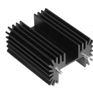 RA-T2X-38E
This is an aluminium vertical mounting heat-sink from OHMITE, model RA-T2X-38E. The weight is 38g with an heat transfer coefficient (natural convection) of 3.9 °C/W.
We will use the weight value to calculate the thermal capacity value, CTH, of the heat-sink. Knowing that the Specific Heat of Aluminium is 0.9 J/g°C we calculate the thermal capacity CTH using:
CTH = m * c
Where:
- m is the mass in grams
- c is the specific heat
This gives us:
CTH = 38g * 0.9 J/g°C = 34.2 J/°C.
Temperature Simulation
We have now got all the element values to run Proteus with a graph simulation of the Junction (green), Case (red) and Heat-sink (light blue)temperatures. We can see that junction temperature will be kept below 90°C @ 50°C ambient temperature. This is well below the maximum junction temperature allowed of 150°C with a reasonable safe margin and tells us that our regulator will work safe providing 1A continuously.
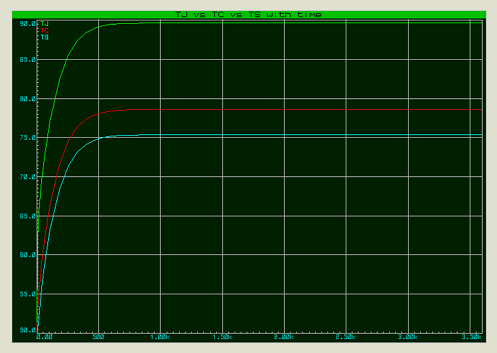 Junction vs Case vs Heat-sink Temperatures.
Conclusion
In a lot of situations we can use these techniques in Proteus to make a prediction analysis of the maximum temperatures that a generic power silicon devices will reach at the rated conditions for safe operations.
All content Copyright Labcenter Electronics Ltd. 2026. Please acknowledge Labcenter copyright on any translation and provide a link to the source content on www.labcenter.com with any usage.Get our articles in your inbox
Never miss a blog article with our mailchimp emails