It is often the case that not all of the components on the schematic are fitted on a particular version of the final PCB. For example, you may have a design in which functionality is removed from a basic or intermediate version of the product. Similarly, you might want to have alternate parts fitted on different versions of the PCB. An example of this is using different pullup and pulldown resistors to indicate the PCB/hardware revision to the microprocessor.
EDA Tools like the Proteus Design Suite can help you manage both of these situations by supporting Assembly Variants. In this post, we’ll look at the rules for using Assembly variants and then how to configure and work with them in your project.
Understanding Assembly Variants
The most important thing to understand from the examples above is that the final etched PCB does not change between variants. Nothing you do in an assembly variant can change the PCB. What you can do therefore is define the fitted status of each part or you can replace a part with a pin-compatible alternative part.
Following on from this is the fact that your standard schematic (normally called Base Design) is the master or superset of all of the variants. An assembly variant is just a deviation from base design.
This means you should always design the product in base design. This holds true even with things like debug headers that won't be present on the production PCB. You can't exclude items from base design so in this case you would most likely create two variants called TEST and PRODUCTION.
Working with Assembly Variants
The details of using Assembly Variants will differ between EDA Tools but the general workflow is similar. After completing the base design, you use the variant organiser (in the Proteus Design Suite this is the Design Explorer) to add or remove variants. Normally, this presents you with a list of the parts on the schematic along with their fitted status and you can change this status for each variant.
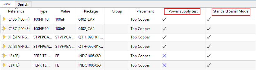 Specifying the fitted status per variant in the Design Explorer of the Proteus Design Suite.
There is a little more work involved if you are switching to an alternative part in a variant because you’ll have to update other relevant information like stock code or supplier.
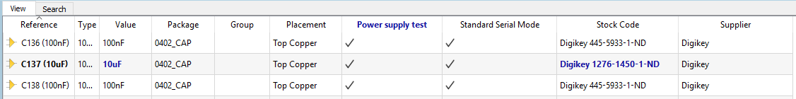 Alternate parts per variant requires additional configuration.
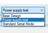
Aside from the variant organiser the other tool you need is the variant selector. This is normally a system global combo box that informs the entire EDA toolsuite (schematic, layout, 3D Viewer etc.) of the current variant. For example, the 3D view of the PCB will not show the component bodies of parts that are designated as not fitted in the selected variant.
Assembly Variants Output
The real benefit of assembly variants comes in the output fileset. In particular, the Bill of Materials for a given variant will correctly represent the fitted status of the parts in that variant and, where necessary, detail the correct stock code and supplier of alternative parts used in the variant.
The assembly drawings for top and bottom are also variant aware and will normally represent a not fitted part with a cross out on the drawing. Similarly, the pick and place file will not include any parts excluded from the active variant.
Some EDA Tools can also produce a variant comparison report to tabulate all of the differences between the various Assembly Variants and the base design.
You can find out more about using Assembly Variants in the Proteus Design Suite by watching the video linked below:
All content Copyright Labcenter Electronics Ltd. 2026. Please acknowledge Labcenter copyright on any translation and provide a link to the source content on www.labcenter.com with any usage.Get our articles in your inbox
Never miss a blog article with our mailchimp emails