Introduction
In the early days of microcontrollers (MCUs), the only way to load program code into their memory was with a programmer – a special hardware tool built for the purpose.
If a products firmware needed to be updated, then it was usually necessary to send the product back to the supplier or have a technician with a programmer go out to the product in the field. Nowadays, it is usually possible to update a microcontroller’s firmware without using a programmer – provided that the microcontroller is equipped with a bootloader program. The reason that this has become possible is due to advances in the type of program memory used in microcontrollers, as well as in the microcontroller architecture; bootloaders work on the premise that a microcontroller can write to its own program memory, essentially programming itself.
EPROM, EEPROM & Flash
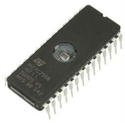
In the early days of microcontrollers, EPROM (Erasable Programmable Read-Only Memory) was used; these chips had a clear window on the top, and were erased by shining a UV light on them.
After EPROM came EEPROM (Electrically Erasable Programmable Read-Only Memory), which could be erased electronically with a programmer. Although EEPROM could be self-programmed and there were a few microcontrollers with this feature it was quickly superseded by the considerably cheaper FLASH memory. FLASH memories originally required high voltages for programming / erasing, supplied by an external programmer, however charge pumps for supplying these voltages were later built into the chips themselves. FLASH is still the standard memory used in microcontrollers today and with self-programming FLASH capabilities on the MCU, bootloaders have become possible.
Bootloaders
The basic premise of a bootloader is that the microcontroller receives new program data via some communication method – be that USB, WiFi, Ethernet, UART, SPI, CAN, SD-card, etc – and writes that new program data onto the chip. At the same time, the bootloader obviously can’t write over itself, so it needs to be segmented off into a separate section of program memory.
If you have read our post about FLASH memory, then you will know that FLASH memory is divided into sectors. One (or more) of these sectors will be reserved for the bootloader program, and the others used for the application program (the code to be bootloaded on). Another approach, if there is sufficient FLASH memory, is to include the bootloader code in the application code itself, have two or more same-sized areas of FLASH reserved for program memory, and ping-pong between these each time a new program is bootloaded on.
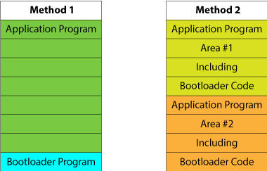
Method 1 is agnostic to the application program code, and can usually load any type of application code written for a particular microcontroller so long as that application code does not also use memory in the sector of FLASH where the bootloader program resides. The application code can work either without a bootloader (programmed straight on using a programmer) or with a bootloader (bootloaded on).
Method 2 requires the bootloader code to be built into the application code each time. If it is not, then no further bootloading will be possible and the device will need to be reprogrammed using a programmer.
Entering Bootloader Mode
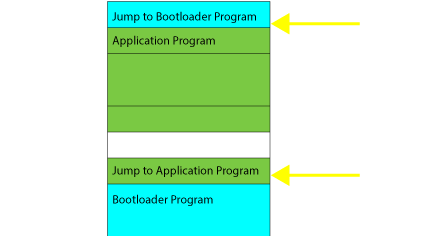
When using methods where the bootloader program is separate to the application program (Method 1), it needs to be decided when to transfer control to the bootloader program. This could be done from the application program upon some condition (e.g. a command received via some communication port or a button pressed), or another technique which can be used is to run the bootloader first briefly (for a few seconds) at startup and check if there is any newer firmware waiting to be downloaded (try to connect to a waiting computer program via USB for example) before transferring control to the application program if not. The advantage with running the bootloader first at startup is that it is not dependent on the application code transferring control to it, so if there is some problem or bug with the application code then it is still possible to recover by resetting the MCU and bootloading another version of the application code onto the chip.
In order to do this, the bootloader needs to make sure that it runs first, which may involve modifying the reset vector in the code. The reset vector is the address in memory where the MCU will start executing code from after reset. The bootloader needs to modify this to divert code execution to itself at startup rather than to the application.
This adjusting of the program (modifying of the reset vector) can be done before the application code is passed to the bootloader, such as by a computer program connecting to the bootloader program via USB, which reduces the code complexity (and size) of the bootloader.Some microcontrollers, such as the ATMEGA328P used in the popular Arduino Uno, have a fuse which can be programmed to move the reset vector, without the need to change anything in the FLASH memory / application program.
Case Study: Arduino Bootloading from SD Card
A Proteus simulation of an Arduino Uno (ATMEGA328P) bootloader, which bootloads new firmware from an SD card, is linked below.
A demo copy of Proteus is required to open the .pdsprj file.
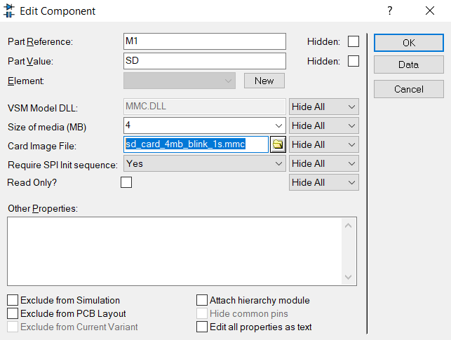
This bootloader, called avr_boot (https://github.com/zevero/avr_boot), looks for a firmware file called FIRMWARE.BIN on an attached SD card, and bootloads the MCU with it if present. In the field, all you would need to do is plug in an SD card with the newer firmware, power on or reset the MCU, and the application code on the MCU would be updated! Two different SD card images are included, with two different programs to be bootloaded. The SD card contents can be changed by editing the SD Card component’s properties on the schematic part:
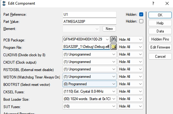
The firmware and bootload fuse settings are specified in the same way, via the Edit Component dialogue form on the AVR microcontroller (right click context menu)
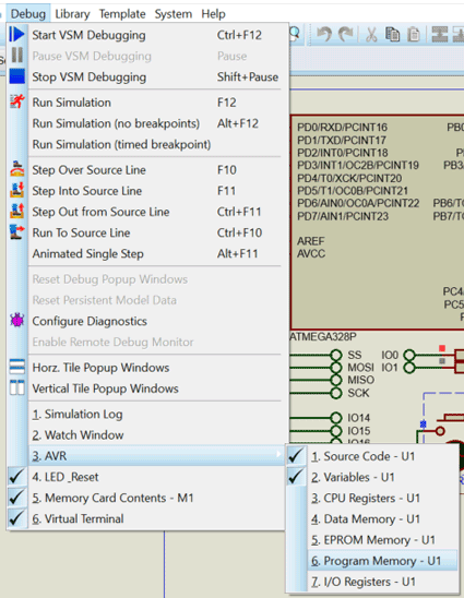
You will probably then want to turn on viewing of the MCUs FLASH memory to see the effect of the bootloading process:
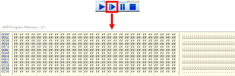
Next, if you start the simulation paused then you should see that the MCU's memory at address 0x0000 is blank:
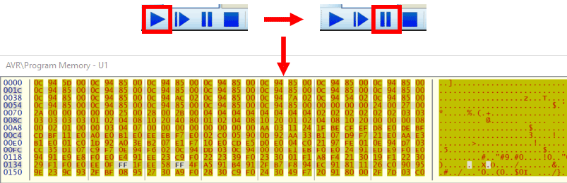
Run the simulation briefly and pause again to see that the flash memory has now been filled with the bootloaded program.
 All content Copyright Labcenter Electronics Ltd. 2026. Please acknowledge Labcenter copyright on any translation and provide a link to the source content on www.labcenter.com with any usage.
Get our articles in your inbox
Never miss a blog article with our mailchimp emails
Advanced Simulation
Learn more about our built in graphing and advanced simulation features. Harness the mixed-mode simulation engine in Proteus to quickly test your analog or digital circuitry directly on the schematic.
 Ask An Expert
Have a Question? Ask one of Labcenters' expert technical team directly.