Introduction
Analogue to Digital Converters (ADCs) convert an analogue voltage to a digital number (for use in a computer, such as a microcontroller). ADCs have a particular resolution, as well as a positive and negative reference voltage. A 10-bit ADC, for example, converts the input voltage to a number between 0-1023 (1023 is the largest number which can be represented with 10-bits). If the negative reference voltage is 0V and the positive reference voltage is 5V, then an ADC result of 0 would means 0V and an ADC result of 1023 would mean 5V. An ADC result of 511 would mean 2.5V, and so on. Each numerical step (the resolution) would be equivalent to approximately 4.9mV (5V/1024).

For more information on Analogue and Digital signals, please see our dedicated article on the topic.
A number of different types of ADCs exist, and in this article we will examine the Successive Approximation [Register] or SAR ADC. SAR ADCs are the type most commonly found in microcontrollers, and offer a good (relatively fast) conversion time (low latency) for typical resolutions.
Anatomy of a SAR ADC
SAR ADCs consist of 3 components:
- Sample and Hold Circuit.
- DAC (Digital to Analogue Converter).
- Comparator.
(The successive approximation register itself, which drives the DAC, may be viewed as a 4th component)

You may wish to check our articles on OpAmps (which includes Comparators) and DACs before continuing.
The sample-and-hold circuit takes a sample of the input voltage and then stores it (keeping it constant and stable) whilst the conversion is done. Conceptually this is simply a switch and a capacitor; the switch closes to charge the capacitor to the input voltage, and then opens again to leave the capacitor to hold the sampled voltage.
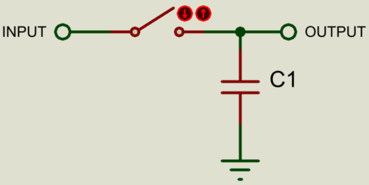
In practice, some buffering opamps (see our OpAmps article) are used to prevent distortion of the voltages.
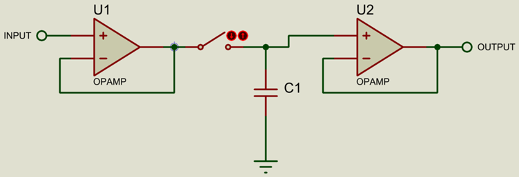
The switch is implemented via a transistor.
Using the DAC and Comparator, a Binary Search is then performed to approximate the value of the input.
Binary Search
A Binary Search is a type of search algorithm which narrows down on the result by continually dividing the search domain in 2 (binary) and checking which side of the search domain the input falls on. Put another way, the algorithm checks whether the input is greater than or smaller than the value in the middle of the search domain. This is perhaps easiest to explain with an example:
Lets say we have a set of numbers, sorted from smallest to largest, and we need to insert another number into the set whilst keeping the set sorted. How would a computer figure out where to insert the number?
Insert 55 into the following set, maintaining the order of smallest to largest.
| 2 | 7 | 15 | 33 | 40 | 45 | 77 | 89 |
One method is to simply start at the beginning of the set and inspect each number one-by-one until we either find a number which is larger than our input (or until we reach the end of the set), and then insert the number just before that. This method may be fast enough for smaller sets of numbers, but as the size of the set increases (to hundreds and thousands of entries) then a search algorithm will be much faster most of the time.
Using the binary search algorithm we divide the search domain into 2, and then check whether our input is larger or smaller than the number in the middle. There isnt exactly a middle, so we implement a rule which says that we use the number just to the right of middle:
| 2 | 7 | 15 | 33 | 40 | 45 | 77 | 89 |
55 > 40, so we narrow our search to the upper part of the search domain, and repeat:
| 2 | 7 | 15 | 33 | 40 | 45 | 77 | 89 |
55 < 77, so we narrow our search to the lower part of the revised search domain:
| 2 | 7 | 15 | 33 | 40 | 45 | 77 | 89 |
55 > 45, so we know that the number falls just to the right of 45 for this set.
For a set of 8 numbers, this process will always take a total of 3 search steps.
SAR ADC Binary Search
The SAR ADC binary search works in the same way, using the DAC to generate the set of numbers to be searched and the comparator to compare the input value to the current search position.
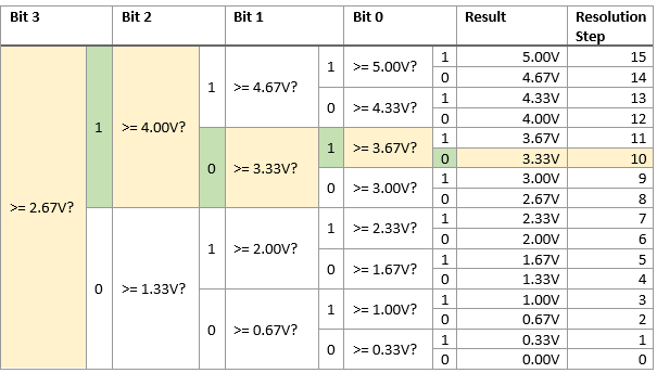
Lets say we have a 4-bit ADC, giving a resolution of 16 steps (values 0-15), a positive reference voltage of +5V (negative reference voltage of 0V), and an input voltage of 3.6V.
We start with a binary value of 1000 in the successive-approximation-register, which is decimal 8 (just above half-way).
| Bit 3 | Bit 2 | Bit 1 | Bit 0 |
|---|---|---|---|
| 1 | 0 | 0 | 0 |
The output voltage from the DAC is then 2.67V (8 / 15 x 5V). The comparator checks and sees that the input of 3.6V > 2.67V, so we leave Bit 3 as 1 and move on to Bit 2, which we now also set to 1 (we always set the next bit to 1 when we move to it).
| Bit 3 | Bit 2 | Bit 1 | Bit 0 |
|---|---|---|---|
| 1 | 1 | 0 | 0 |
The DAC output is now 4V, so the comparator checks and sees that the input of 3.6V < 4V, so we set Bit 2 to 0 and move to Bit 1, also setting it to 1.
| Bit 3 | Bit 2 | Bit 1 | Bit 0 |
|---|---|---|---|
| 1 | 0 | 1 | 0 |
The DAC output is now 3.33V, so the comparator checks and sees that the input of 3.6V > 3.3V, so we leave Bit 1 as 1 and move onto Bit 0, also setting it to 1.
| Bit 3 | Bit 2 | Bit 1 | Bit 0 |
|---|---|---|---|
| 1 | 0 | 1 | 1 |
The DAC output is now 3.67V, so the comparator checks and sees that the input of 3.6V < 3.67V, so we set bit 0 to 0 and the conversion is now complete.
| Bit 3 | Bit 2 | Bit 1 | Bit 0 |
|---|---|---|---|
| 1 | 0 | 1 | 0 |
An input of 3.6V on a 4-bit ADC with a positive reference voltage of +5V (and negative reference voltage of 0V) converts to a binary value of 1010 (decimal 10).
Drawn another way, this process looks as follows:
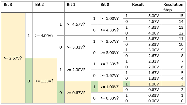
Here is another example, for an input voltage of 1.10V:
Note that the binary search algorithm always takes a fixed number of steps to complete, which means that it always takes the same amount of time to run the conversion.
Summary
SAR ADCs are a popular type of Analogue to Digital Converter which have a relatively fast conversion time for typical resolutions. Because the binary search algorithm which these ADCs use always takes a fixed number of steps, the conversion time is predictable.
All content Copyright Labcenter Electronics Ltd. 2026. Please acknowledge Labcenter copyright on any translation and provide a link to the source content on www.labcenter.com with any usage.Get our articles in your inbox
Never miss a blog article with our mailchimp emails
Advanced Simulation
Learn more about our built in graphing and advanced simulation features. Harness the mixed-mode simulation engine in Proteus to quickly test your analogue or digital circuitry directly on the schematic.
 Ask An Expert
Have a Question? Ask one of Labcenters' expert technical team directly.