This article complements our other blog post primer on boost converters. If you want to take a low voltage up rather than a high voltage down then you can read about boost converters here.
Buck converters efficiently reduce a higher voltage to a lower voltage. In the past this was usually done with linear voltage regulators (which simply dissipate the excess voltage as heat), however buck converters are far more efficient – especially when the differences in voltage are large.
The inductor is also the star of the Buck Converter circuit.
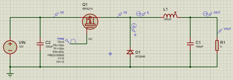
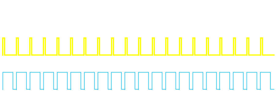
In the mechanical analogy we used in the boost converter post we likened the inductor to a flywheel. For buck converters this flywheel is not used to generate spikes of high force (voltage) by spinning it up and then trying to suddenly stop it. Instead, it is rather kept spinning at a constant speed by constantly tapping it with just enough energy to keep it going at that particular speed. When the switch is not on, then current flows through the freewheeling diode so there is no sudden stop force on the inductor. The above buck sample design in Proteus provides the simplest example of such a circuit. The switch is driven on and off rapidly, using a high-frequency PWM (Pulse Width Modulated) signal.
Another way to think of this is like a heavy merry-go-round (which is essentially a flywheel).

If you stand at the side of the merry-go-round and only tap it momentarily every 10s, then it will not spin around very fast (depending on how much resistance – load – there is in the system). Tap it every 1s and it will spin faster. Give it a more sustained push every 1s and it will spin even faster.
The merry-go-round has a freewheeling diode built in, in that it has a bearing in the middle which allows it to keep spinning unhindered when you’re not actively pushing it.
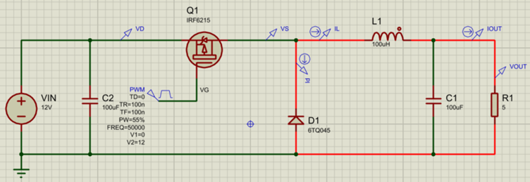
Translating this into electronics, in our circuit Q1 is the switch (driven by the PWM), L1 is the inductor, D1 is the freewheeling diode and R1 is the load. Capacitor C1 helps to smooth the output voltage.When the switch (Q1) is on, then current flows through the circuit from the battery.
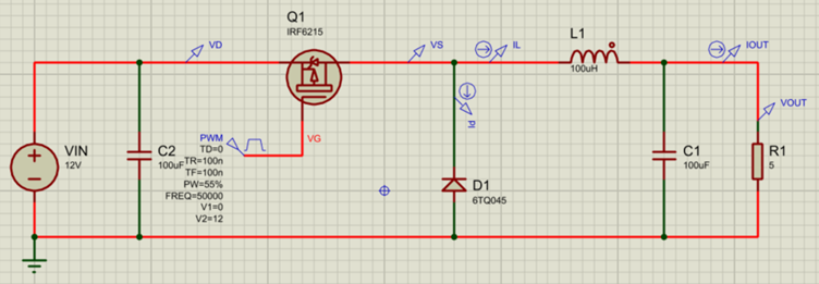
When the switch (Q1) is off, then current continues to flow through the load from the energy stored up in the inductor, with the freewheeling diode completing the circuit in this case.
Whilst this circuit provides a simple explanation for how a buck converter works, it cannot maintain a constant output voltage as the load changes. For this, a Buck Controller is needed.
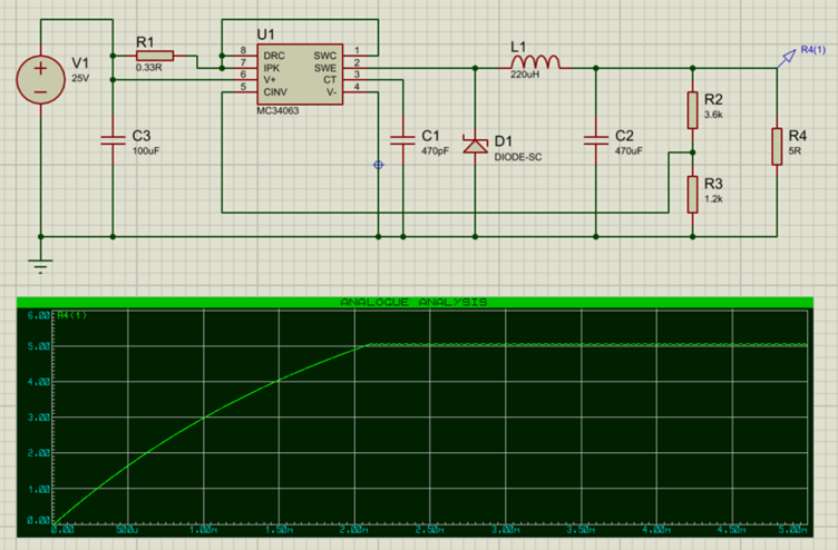
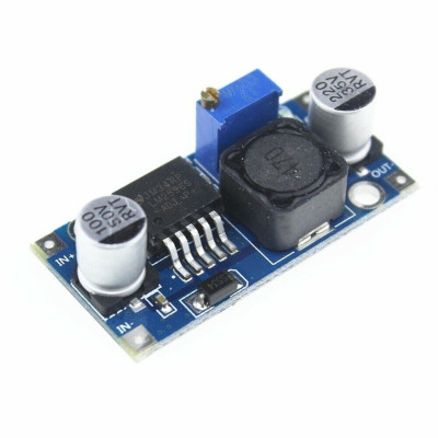
In the above circuit, an MC34063 Buck Converter is used to step 25V down to 5V. The switching transistor is integrated inside the controller, and so an external one is not required. The controller monitors the output voltage using the feedback resistors R2/R3, and maintains a constant output voltage at the load.
A demo copy of Proteus is required to open the .pdsprj file.
Summary
Buck and Boost converters are smart and efficient ways to convert voltages down or up. If you would like to experiment with them, then Proteus provides a great simulation environment for easily changing designs and analysing operation.
All content Copyright Labcenter Electronics Ltd. 2026. Please acknowledge Labcenter copyright on any translation and provide a link to the source content on www.labcenter.com with any usage.Get our articles in your inbox
Never miss a blog article with our mailchimp emails
Advanced Simulation
Learn more about our built in graphing and advanced simulation features. Harness the mixed-mode simulation engine in Proteus to quickly test your analog or digital circuitry directly on the schematic.
 Ask An Expert
Have a Question? Ask one of Labcenters' expert technical team directly.