Floating Inputs
This article assumes a familiarity with Digital Signals – if you are not already familiar with the concept of digital (as opposed to analogue) signals then please read our article on the topic first.
First, let’s consider the case of a two-way (single-pole double-throw) switch:
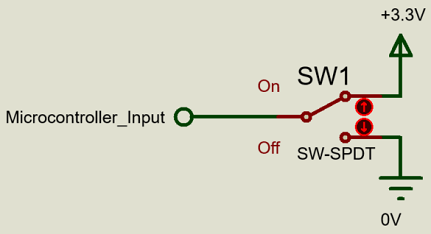
When the switch is on, then the microcontroller input will be connected to +3.3V meaning high. When the switch is off, then the microcontroller input will be connected to 0V meaning low. What if we have a single button however?
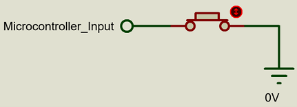
When the button is pressed, then the microcontroller input will be connected to 0V meaning low. When the button is not pressed however, then the microcontroller input is not really connected to anything:
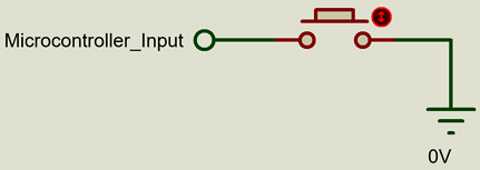
It is the same as if nothing was connected at all:

What will the input level be in this case? High or Low? Because it is not really connected to anything, the input could be anything, depending on the static electricity or electro-magnetic radiation in the environment. It may simply pick up radio waves (like an antenna) and flop around back-and-forth between weakly-defined states of high and low. This state, where the microcontroller input is not well-defined and could be anything (random) is called floating.
Pull-up and Pull-Down Resistors
In order to fix this, what is done is to add a pull-up resistor or pull-down resistor to the input (pull-up resistor illustrated below):
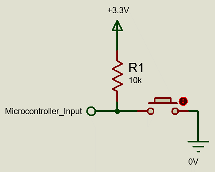
When the button is not pressed, then the pull-up resistor will pull the microcontroller input up to +3.3V, providing a well-defined high. When the button is pressed, then the microcontroller input will be directly connected (short circuited) to ground (0V), providing a well-defined low. Some current will flow through the pull-up resistor in this case, however it will be a small amount due to the relatively high value of the resistor.
You may notice that the resistor symbol looks like a little spring, and that is exactly how it functions in this case. We’ve all used automatically-closing doors, such as are commonly found in public facilities – unless you actively hold the door open, then there is a mechanism which will pull it closed again. Without the auto-close mechanism (and imagining for now that the door does not have a latching mechanism), the door would be blown around by the wind or moved around by the people coming in and out, and it wouldn’t default to any particular position. A pull-up (or pull-down) resistor is similar to the auto-close mechanism on these doors, in that it keeps the input at a particular level when it is not actively being driven. So the pull-up resistor is like a spring on an automatically-closing door – unless somebody strong enough comes and pushes the door open, the door will default to the closed position.
The situation could obviously be reversed, in that the button could connect to +3.3V (high) and a pull-down resistor could be used to keep the input low otherwise:
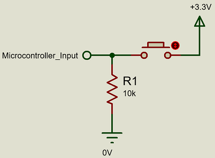
The pull-up resistor configuration is however far more commonly used.
Open Drain Outputs
Some microcontroller outputs can be set as open-drain (or are only available as open-drain). An open-drain output is an output which can only be driven low, not high; the output is either low or floating. Essentially the output is simply connected to the drain pin of a transistor (hence the term open-drain).
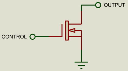
When the Control line is driven high then the transistor short-circuits the Output to ground (0V), pulling it low. When the Control line is driven low then the transistor is high-impedance (high-resistance) and the Output is floating.
Some communication schemes, such as I2C and CAN, use this arrangement to allow multiple devices to communicate over the same communication lines without the possibility of short-circuit (collision, where one device is trying to drive the line high and the other trying to drive it low); in these cases a pull-up resistor is used to hold the line high when it is not actively being driven low.
All content Copyright Labcenter Electronics Ltd. 2026. Please acknowledge Labcenter copyright on any translation and provide a link to the source content on www.labcenter.com with any usage.Get our articles in your inbox
Never miss a blog article with our mailchimp emails
Advanced Simulation
Learn more about our built in graphing and advanced simulation features. Harness the mixed-mode simulation engine in Proteus to quickly test your analogue or digital circuitry directly on the schematic.
 Ask An Expert
Have a Question? Ask one of Labcenters' expert technical team directly.