Introduction
Digital to Analogue Converters (DACs) convert a digital number (used in computers, such as microcontrollers) to an analogue voltage. They are the opposite of Analogue to Digital converters (ADCs).
For more information on Analogue and Digital signals, please see our dedicated article on the topic.
There are two main types of Digital to Analogue Converter (DAC): Binary Weighted and R-2R.
Binary Weighted DAC
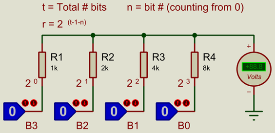
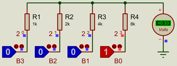
Pictured above is a 4-bit Binary Weighted DAC. If you are not yet familiar with the binary number system, then please see our article on number systems. The DAC can take a number between 0-15 (decimal, binary 0-1111), and generate a corresponding analogue voltage. If the supply voltage is 5V (the logic state blocks switch between 0V and 5V) then, then the voltage steps are 5V/15 = 0.333V.
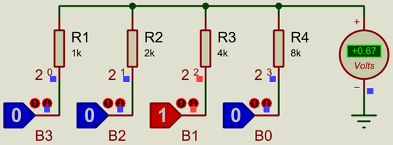
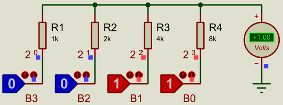
The value of each resistor is:
k x 2(t-1-n)
where:
- t is the total number of bits (4 in this case).
- n is the number of the particular bit (zero based).
- and k is an arbitrary constant (1k in the pictured example).
Of course to drive any sort of load from this DAC, we will need to put it through a buffering opamp (please see our article on opamps for more information):
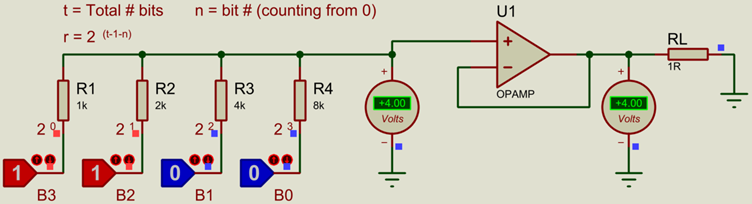
More bits (higher resolution) can be added simply by adding more inputs with resistors of the correct values.
The disadvantage of the Binary Weighted DAC is that a potentially large number of precision-value resistors are required (inflating the BoM), and it may be difficult to find precision resistors in the exact values required.
R-2R DAC
The R-2R DAC requires only 2 values of resistor, one being twice the size of the other.
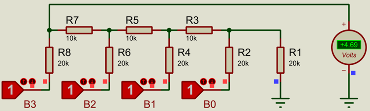
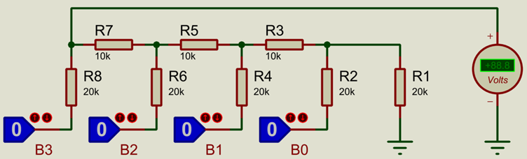 4-Bit R-2R DAC with R=10k (2R=20k)
The disadvantage with the R-2R DAC is that the output voltage is limited to
(2t-1)2t
of the supply voltage, where t is again the total number of bits.
Another way to think about this is that the output voltage is limited to (resolution-1)/resolution of the supply voltage, where resolution is the resolution of the DAC (16 steps for a 4-bit DAC).
For a 4-bit ADC with a 5V supply, this would be 15/16 x 5V = 4.69V
This can however be corrected with a precise amplifier gain, as we will see later.
The voltage steps for a 5V supply and 4-bit DAC, taking into account the output voltage limit for a 4-bit network of 4.69V, are 4.69V/15 = 0.31V.
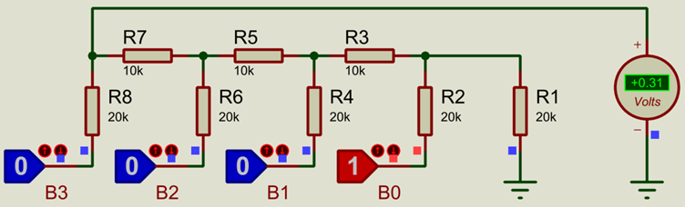
Again, this can be corrected to be over the full supply voltage, using a precise amplifier gain, which would give the 0.333V (same as the Binary Weighted DAC):
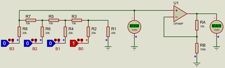
Similar to the Binary Weighted DAC, an amplifier is required if any load is to be driven. To scale the output back to the full supply range, a gain of
2t/(2t-1)
can be used on the amplifier, where t is again the total number of bits.Or, again, put another way, the opamp gain should be resolution/(resolution-1) where resolution is the resolution of the DAC (16 steps for a 4-bit DAC).
This means setting RA=R (10k in this example) and
RB= R x 2t-1
For a 4-bit DAC this would be R x 15, which would be 10k x 15 = 150k in this example. We can then get the full 5V output:
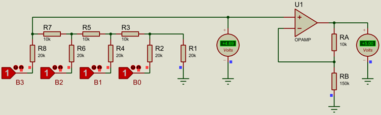
Thus a single precision resistor of an arbitrary value is required in order to scale to the full supply range, however this is arguably easier to handle than the series of precision resistors required for the Binary Weighted DAC.
Additional Types of DACs
Another type of DAC is the Filtered PWM type, where a PWM signal is low-passed through an R-C filter network (as described in our PWM signals article), however this requires relatively complicated circuitry to generate the PWM and does not have as fast a response time as the purely resistive DAC types covered here.
In the Proteus Design Suite you'll find example circuits including digital to analogue converters amongst our sample designs library. All of these and more can be simulated for a trial period in the demo version.
All content Copyright Labcenter Electronics Ltd. 2026. Please acknowledge Labcenter copyright on any translation and provide a link to the source content on www.labcenter.com with any usage.Get our articles in your inbox
Never miss a blog article with our mailchimp emails
Advanced Simulation
Learn more about our built in graphing and advanced simulation features. Harness the mixed-mode simulation engine in Proteus to quickly test your analogue or digital circuitry directly on the schematic.
 Ask An Expert
Have a Question? Ask one of Labcenters' expert technical team directly.