Introduction
Matrix Keypads are an efficient way of reading an array of buttons. Some examples of these include the dial pad on a telephone, the keypad on a point-of-sale (credit-card payment) machine, computer keyboards, or even the keyboard on an electric piano.
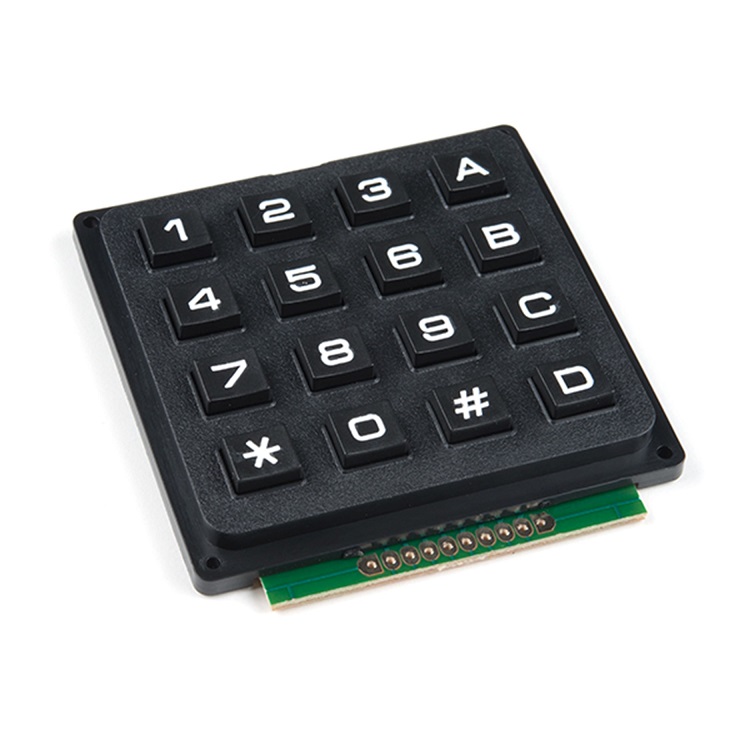
One way to read a large number of button inputs is to connect each button to its own microcontroller input pin. For a 4x4 keypad this would require 16 GPIOs (general purpose input/output) pins.
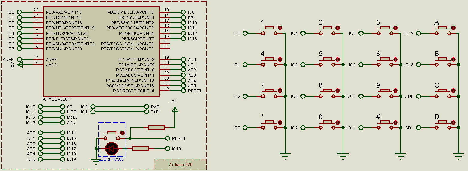
By wiring the buttons in a matrix however, the same number of buttons can be read with only 8 GPIOs.
This reduces the number of microcontroller pins needed, as well as the quantity of associated wiring / number of PCB tracks.
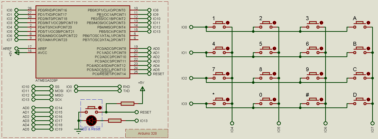
Matrix Keypads are wired in a grid of rows and columns (although they don’t physically have to be laid out in that orientation, such as in the example of the keyboard of an electric piano). On the microcontroller, either the row or column pins are set permanently as inputs (we’ll stick with using the row connections for this purpose in this article), and the other set of pins (we’ll stick with using the column connections for this purpose in this article) toggle between outputs (driven low) and floating (essentially open-drain outputs).
The row input pins need pull-up resistors on them, which could be added external to the microcontroller or possibly activated inside the microcontroller (if the microcontroller includes this feature). Some microcontrollers feature open-drain output pins (for the columns), or alternatively the pins can simply be set as inputs in order to make them float.
If you’re not familiar with the terms pull-up resistor, floating and/or open-drain, then here are some quick explanations:
Some Definitions
A floating input is an input which is not actively driven to any particular level, and could really be anything (based on the static electricity in the environment, for example). We’ve all used automatically-closing doors, such as are commonly found in public facilities – unless you actively hold the door open, then is a mechanism which will pull it closed again. Without the auto-close mechanism (and imagining for now that the door does not have a latching mechanism), the door would be blown around by the wind or moved around by the people coming in and out, and it wouldn’t default to any particular position.
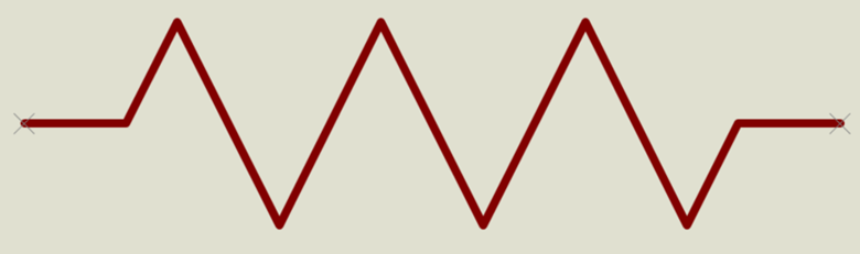
A pull-up (or pull-down) resistor is similar to the auto-close mechanism on these doors, in that it keeps the input at a particular level when it is not actively being driven. The pull-up (or pull-down) resistor can be thought of as a spring which pulls the input to a particular level when it is not actively being driven, and you may notice that the resistor symbol actually looks like a little spring:
An open-drain output is an output which can only be driven low, not high; the output is either low or floating. Essentially the output is simply connected to the drain pin of a transistor (hence the term open-drain).
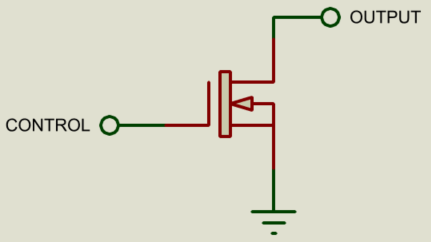
A similar effect can be achieved by toggling the microcontroller pin between being an input (floating, no pull-up or pull-down resistor) and an output which is driven low.
Reading a Matrix Keypad
In order to read any particular button in the matrix, we drive the corresponding column pin low and then read the corresponding row pin; if the row pin reads low then the button is pressed, if it reads high then the button is not pressed.
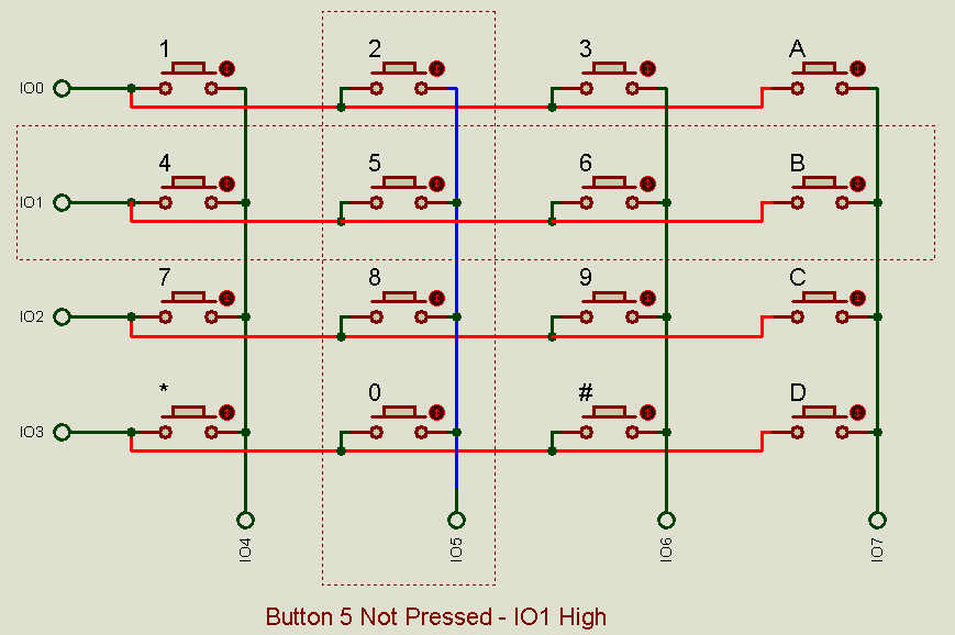
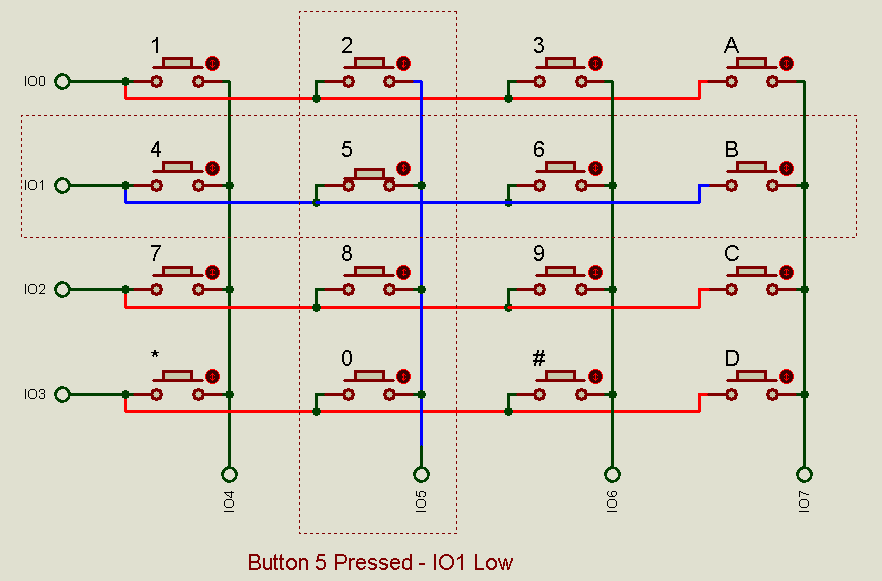
Often this is done in a fast sequential scanning operation to check each button in the matrix, driving each column pin low in turn whilst reading each row pin in between. Simultaneous keypresses do not pose any problem to this method, and it is still possible to read each key individually.
Debouncing
Mechanical switches can also suffer from a phenomenon known as bounce, where the contact of the switch physically bounces when making contact and which results in a few fast voltage transitions before the switch settles in the new state:
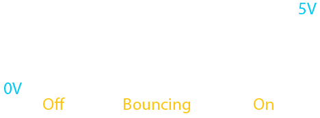
If the microcontroller is reading the input very frequently then it may register the bounces as a number of button presses (instead of just one press, which is what the user expects); the simplest solution to this is to simply leave some delay between each subsequent read of the button, which will give the button enough time to transition in between reads (usually 10-50ms is sufficient). These sort of techniques are known as debouncing the switch.
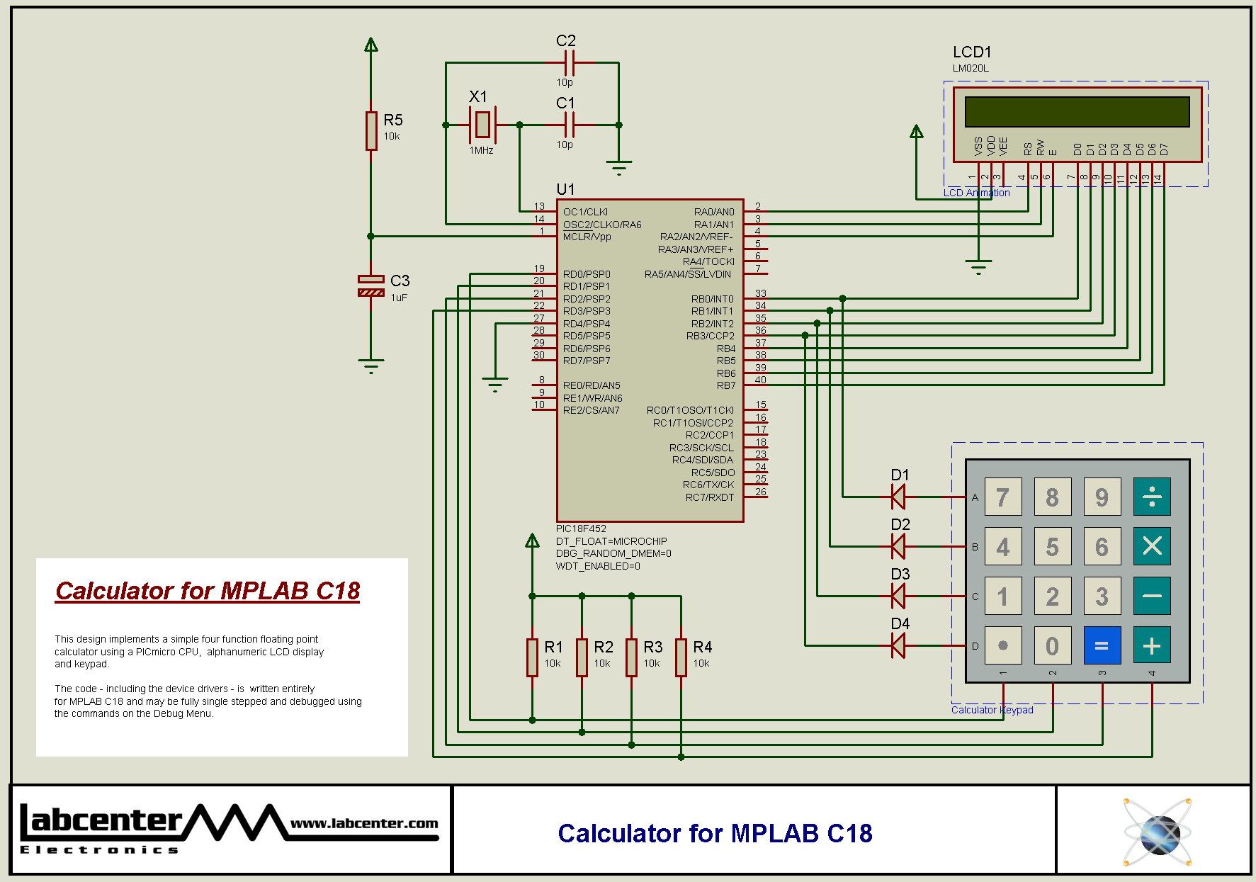
Proteus includes several matrix keypad simulation models and sample projects which can all be tried in the demo version.
 All content Copyright Labcenter Electronics Ltd. 2026. Please acknowledge Labcenter copyright on any translation and provide a link to the source content on www.labcenter.com with any usage.
Get our articles in your inbox
Never miss a blog article with our mailchimp emails
Advanced Simulation
Learn more about our built in graphing and advanced simulation features. Harness the mixed-mode simulation engine in Proteus to quickly test your analogue or digital circuitry directly on the schematic.
 Ask An Expert
Have a Question? Ask one of Labcenters' expert technical team directly.