Introduction
UART is a communications protocol, used to send data from one device to another. Of the popular microcontroller communications protocols (UART, SPI and I2C), UART was the first to be developed.
UART stands for Universal Asynchronous Receiver and Transmitter. Synchronous protocols have separate lines for Clock and Data and the clock line is used to trigger reading (or writing) of the data line. UART is asynchronous, meaning that it only has data line(s) and no clock line. Instead of using a clock line, data is transmitted at a particular speed and both the receiver and transmitter need to be set to the same speed (called the baud rate) for communication to occur successfully.UART usually has 2 data lines, namely Transmit (Tx) and Receive (Rx), and so data can be sent in both directions at the same time (full duplex).
The UART Frame
The UART data line idles high when no data is being transmitted. Data transmission starts by pulling the line low for 1 bit. After the Start Bit, Data Bits are transmitted. This is followed by a Stop Bit where the line is high again.

For example, here is the transmission of the binary number 01011110 (hexadecimal 0x7A):

Some variations on the framing are possible, however the framing setup illustrated above is by far the most common. More details on framing variations follow later in this article. Multiple bytes are chained directly after one another, with no idle time needed in between; for example, below is the hexadecimal sequence 0x1A9E2B:

Baud Rate
The speed at which communication occurs is called the baud rate. Baud Rate is specified in bits per second (bps), and popular rates are 9600, 19200 and 115200. For a framing setup with 1 stop bit and no parity bit (more on that later), it takes 10 bits to transmit 8 data bits (1 byte); so at 9,600 baud this means that the data rate is 960 bytes per second or a little over 1 millisecond per byte.
Because the protocol is asynchronous and no clock is used, both the transmitter and receiver need to use their internal clocks (such as the system clock in a microcontroller) to time the signal. Sometimes it may not be possible for the transmitter or receiver to generate the exact baud rate requested, as the possible baud rates are usually a factor of the internal clock speed of the transceiver – in this case the actual baud rate will deviate from the requested baud rate by a certain percentage, but so long as the deviation is within a certain tolerance then communication should still work fine; usually 3% is about the maximum deviation possible for communication to still occur successfully. The microcontroller (or other transceiver) datasheet can usually be checked to calculate the exact baud rates possible (and therefore also the % deviation for other rates).
Autobauding
Some systems support autobauding, where the receiver will automatically detect the baud rate after analysing some data received from the transmitter. This is done by measuring the width of the smallest pulse in the data – for example if the smallest pulse width is 8.68µs then the baud rate is 115200bps.
Flow Control
UART can optionally have additional flow control lines, which indicate to the transmitter when the receiver is busy and unable to immediately receive more data. This can be useful, for example, where a radio modem (such as a BlueTooth module) is taking the data received via UART and transmitting it over-the-air, and the over-the-air data rate is slower than the UART data rate (even perhaps temporarily, such as if the airwaves are congested with other traffic). The flow control lines are called Request to Send (RTS) and Clear to Send (CTS), and the RTS line of one transceiver is wired to the CTS line of the other transceiver and vice versa. The transceiver which wants to transmit monitors the CTS line of the other transceiver (connected to the first transceiver’s RTS pin), which sets the CTS line high when it is ready to receive data.
Protocol Variations
By far the most used variation of the UART protocol is 8N1 which is short for:
- 8 Data Bits.
- No Parity Bit.
- 1 Stop Bit.
The number of data bits used can vary between 5 and 9 (although most microcontroller UART peripherals only support either 8 or 9 bits). Where a 9th bit is used, then this is often used to indicate whether the frame is a data or a control message.
Having 2 stop bits provides an additional error-check on the frame (if both stop bits are not present then there is an error).
Parity is another form of error-checking where an additional bit is set in order to make the number of 1’s in the frame even or odd. For example: For even parity, if the number of 1’s in the data is 3 then for the parity bit will be set so that the number of 1’s in the frame will be 4 (even). For odd parity, if the number of 1’s in the data is 4 then the parity bit will be set so that the number of 1’s in the frame will be 5 (odd).
You'll find lots of examples of different UART simulations in our sample designs portfolio and can easily set up test jigs using the RS232 (TTY) terminal model and a microprocessor in Proteus.
Protocol Errors
Various protocol errors can occur, where the signal does not conform to the UART standard, and many microcontrollers have built-in hardware support for detecting and reporting these errors. Errors may occur because of interference in the communication line (such as ElectroMagnetic Interference i.e. EMI), mismatched protocol setup, or mismatched baud.
- Framing Error: The stop bit(s) was not detected at the expected position.
- Parity Error: The parity is incorrect.
- Noise Error: Transitions (pulses) were detected on the line which are shorter than the baud rate. Some microcontrollers have an oversampling feature where the UART line is read more than once per bit, and this feature is used to detect noise.
Wiring
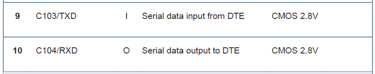
A very common (and easy-to-make) mistake with UART is to wire the communication incorrectly – it is important to remember that Rx on the one side goes to Tx on the other side, and vice-versa. The same applies for flow control lines – RTS on one side goes to CTS on the other side and vice-versa. To make matters worse, some manufacturers label the pins on their peripheral devices according to where they should be connected on the host! So on these devices Rx on the host does get connected to Rx on the peripheral (and so on). It is always a good idea to double-check your UART wiring, making use of the device datasheets. For example, here is an excerpt from one GSM-module datasheet where the pins are labelled from the module-point-of-view:

And here is an excerpt from another GSM-module datasheet where the pins are labelled from the host-point-of-view:
The SPI naming scheme of MISO (Master-In-Slave-Out) / MOSI (Master-Out-Slave-In) is much better at avoiding these sorts of silly (and costly) mistakes, however this alas does not apply to UART – when drawing your schematic however, it can be helpful to name nets thoroughly (such as BlueTooth_Tx) which will help to avoid mistakes.
Physical Layer
UART communication can take place over various physical hardware schemes. Some of these are TTL, RS232 and RS485:
- TTL stands for Transistor to Transistor Logic (see our Analogue and Digital Signals article) and is suitable for short-distance communication. High is usually 5V or 3.3V, and low 0V.
- RS232 used to be common on computers, but was replaced by USB. A high with RS232 is between -3V to -15V, and a low is between 3V to 15V. Since RS232 has been replaced by USB, USB-to-serial converter chips have become common (such as the ubiquitous FT232) which present as a Virtual COM Port on the computer.
- RS485 is a differential-pair implementation, which is better at being immune to electromagnetic interference (EMI) and communicating over longer distances. Please see our High Speed Design article for more information on Differential Pairs.
Summary
Despite being one of the earliest communications protocols to be developed, UART is still as relevant and popular today as ever, and a little understanding of the protocol can help to understand how it can be best implemented in your applications as well as how to debug any issues (such as with an oscilloscope). Proteus provides both Virtual Terminal and Oscilloscope instruments for working with UART under simulation, besides for having a plethora of UART-enabled devices available from the component libraries.
All content Copyright Labcenter Electronics Ltd. 2026. Please acknowledge Labcenter copyright on any translation and provide a link to the source content on www.labcenter.com with any usage.Get our articles in your inbox
Never miss a blog article with our mailchimp emails
Advanced Simulation
Learn more about our built in graphing and advanced simulation features. Harness the mixed-mode simulation engine in Proteus to quickly test your analogue or digital circuitry directly on the schematic.
 Ask An Expert
Have a Question? Ask one of Labcenters' expert technical team directly.