Some History
Removable computer memory has evolved through a number of different mediums over the years.Initially removable disks were magnetic – Floppy and then Stiffy disks.
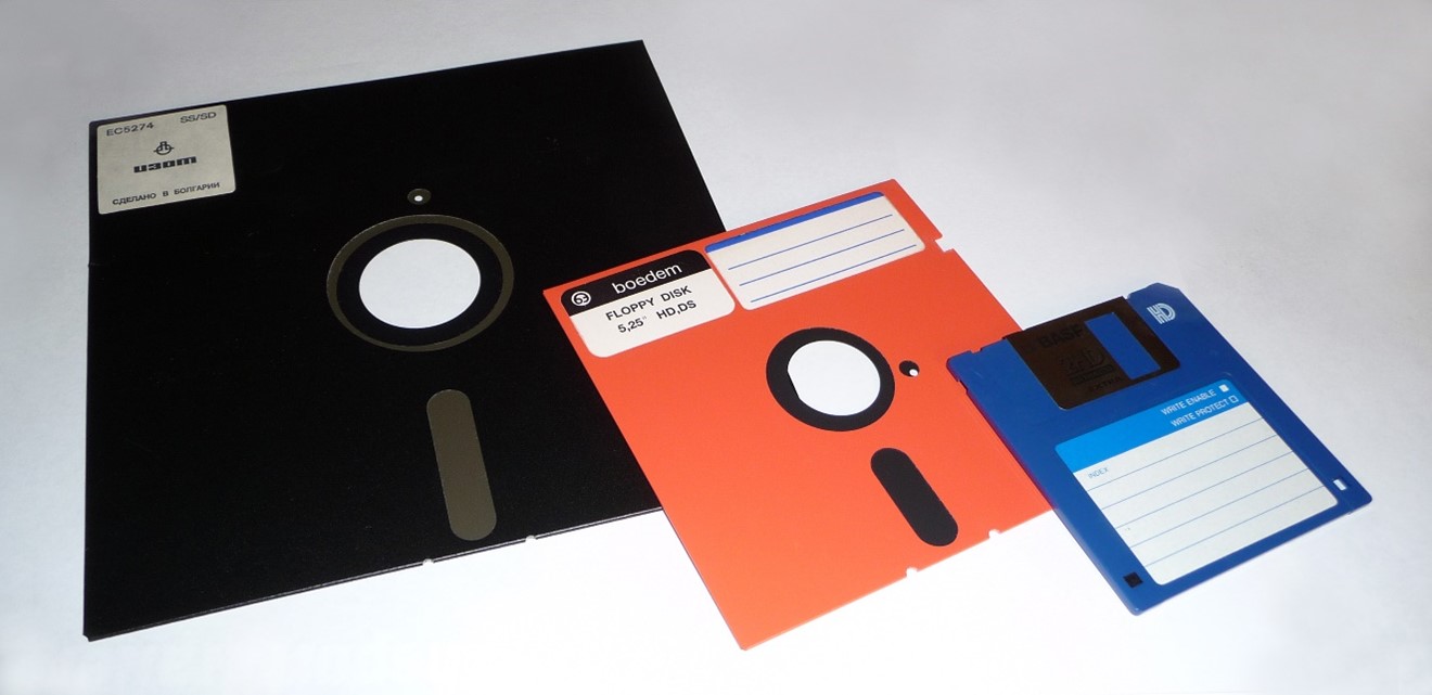 From left to right: 8inch Floppy, 5.25inch Floppy and 3.5inch Stiffy disk.
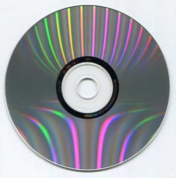
In the 1990s removable storage transitioned to the optical Compact Disk medium (later surpassed by DVDs).
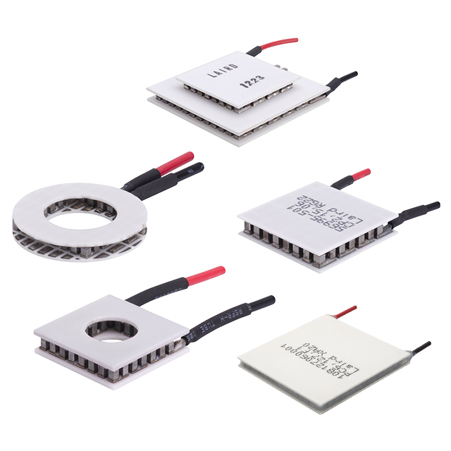
In the 2000s, due to advances in FLASH memory technology, FLASH-based removable storage became popular. Initially this was mostly in the form of USB thumb drives. A number of competing memory card formats also emerged; including the Sony Memory Stick, CompactFlash (CF), xD-Picture Card, Toshiba SmartMedia, and MultiMediaCard (MMC); the Secure Digital (SD) Card however ultimately gained the most market traction.
SD Cards are similar to MMC cards (and are indeed derived from MMC cards), however SD Cards are slightly thicker (2.1mm vs 1.4mm for MMC) and were developed to add a DRM (Digital Rights Management) feature to combat music piracy. In general, SD Cards are backwards compatible with MMC cards, meaning that MMC cards can be used where an SD Card is supported (but not necessarily the other way around). MMC and SD continue to coexist, with SD being more popular for removable memory and MMC (in the form of eMMC) being more popular for solder-down storage in embedded systems.
Form Factor
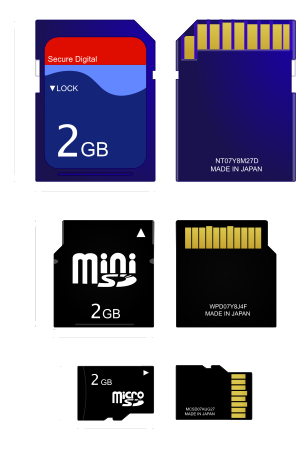
SD cards come in 3 form factors. Originally there was the full-size SD, which was followed by the miniSD and then the microSD.
Communications Interface
The pinout for SD cards is as follows:
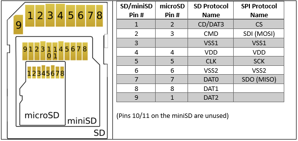
SD cards support two communications protocols: SD Bus and SPI Bus (there are also UHS-II Bus and PCIe Bus protocols supported by some newer cards with additional pins, however SD Bus and SPI Bus are by far the most common).
As practically all modern microcontrollers include an SPI peripheral, SPI is a popular means for embedded developers to communicate with SD cards.
For more information on SPI, please see our dedicated article covering the protocol
Some microcontrollers also include an SDIO peripheral for communicating with SD cards. Because the SD bus protocol can transfer data up to 4-bits at a time (over pins DAT0-DAT3), and because it has a separate command (CMD) line, data transfers using SD bus can be 4-5x faster than using SPI bus (which can only transfer data 1-bit at a time). SD bus starts in 1-bit mode, but can be set to 4-bit mode by issuing the appropriate commands.
Cards start in SD bus mode (1-bit) by default, but can be set to SPI mode by sending a specific command (CMD0) whilst holding the CS line low. Because the SD bus CMD pin is the same as the SPI bus MOSI pin, and because the SD bus CLK pin is the same as the SPI bus SCK pin, the MCU SPI controller can be used to issue the command.
This article will not attempt to cover the full SD card command set or communications protocol. The specification is available from the SD Association at https://www.sdcard.org/downloads/pls/ (or sometimes it can be easier to check the specification document from an SD card manufacturer), however most developers will simply use an existing code library rather than writing their own from scratch.
Data Storage
Reading from and writing to SD cards is done in blocks, usually 512 bytes in size. A File System storage scheme, such as FAT16 or FAT32, is usually implemented on the cards (as a conceptual layer on top of the raw FLASH memory). File Systems are structured methods of storing data (in files and directories), and are handled by software on the host (microcontroller or computer) – not by the SD card itself. Again, most developers will choose to simply use an existing File System library rather than writing their own from scratch.
The FAT16 file system is simpler and was popular until SD cards of 2GB or smaller started becoming scarce, because 2GB is the maximum size that FAT16 can handle. FAT32 can handle file systems up to 16TB in size. As 2GB or smaller SD cards have become more difficult to find (due to no longer being manufactured), many developers have been forced to migrate their projects from using a FAT16 file system to using FAT32.
Reliability
SD cards use FLASH memory internally (for more information please see our dedicated article on FLASH memory), and as such data is erased in blocks – usually of a size of a few kilobytes or larger. Thus, it may be necessary to erase and rewrite much of an entire memory block in order to write some new data. Because this operation takes a little time, if power is lost in the process then data may be lost and the file system corrupted. Additionally, the FAT library may cache data in the MCU (microcontroller unit) or MPU (microprocessor unit) RAM in order to reduce the number of erase-write operations in the FLASH memory (reducing wear-and-tear on the memory, as it has a limited number of erase-write cycles which can be performed) and so again if power is lost or the system crashes then data will be lost.
Because FLASH memory has a limited number of erase-write cycles which can be performed on it, some SD cards include a wear-levelling feature in their internal controller, which automatically distributes erase-write operations evenly over the entire area of FLASH memory (invisibly to the user, as it automatically translates physical memory addresses to virtual memory addresses).
Industrial SD cards are available, which offer increased reliability and endurance. These cards come with controllers implementing features such as wear-levelling and ECC (error correcting code), and higher-end cards also use SLC (single-level-cell) or pSLC (pseudo-single-level-cell) FLASH memory technology instead of MLC (multi-level-cell) technology. MLC is a technology which stores multiple bits per memory cell – decreasing cost but also decreasing reliability and endurance. For remote and safety-critical / high-reliability applications, industrial SD cards are recommended.
Voltage Levels
SD cards operate at 3.3V by default, and so voltage translators are needed to interface them with 5V microcontrollers. SDHC and SDXC cards can switch to 1.8V operation on command, which is better for high-speed signalling.
Simulation Support
Proteus includes MMC/SD card simulation models with SPI interfaces, which can be hooked up to the variety of microcontrollers which Proteus also supports under simulation. Additionally, the SPI communication between the microcontroller and the MMC/SD card can be debugged using the SPI Debugger Virtual Instrument.
You can download the demo version and experiment with writing and accessing data from SD/MMC Cards. There are also a couple of ready-made sample designs with code examples and blank FAT32 images.
All content Copyright Labcenter Electronics Ltd. 2026. Please acknowledge Labcenter copyright on any translation and provide a link to the source content on www.labcenter.com with any usage.Get our articles in your inbox
Never miss a blog article with our mailchimp emails
Advanced Simulation
Learn more about our built in graphing and advanced simulation features. Harness the mixed-mode simulation engine in Proteus to quickly test your analogue or digital circuitry directly on the schematic.
 Ask An Expert
Have a Question? Ask one of Labcenters' expert technical team directly.