Proteus includes fully design rule aware manual routing in both push and shove and traditional follow-me routing modes. Cornering can be either mitred or curved and a forward looking algorithm means that routes being placed can be auto-completed at any time. Routing modes and configuration can be changed mid-route by keyboard shortcut or in the Route Command Centre. Proteus also includes support for high speed net tuning and comes with a dedicated differential pair routing mode.
- Full support for Push and Shove Routing including via nudging.
- Toggle between Push mode and Hug mode (follow me routing).
- Fully design rule aware routing including curved routing.
- Full support for Push mode route editing modes.
- Smart vias use drill ranges automatically when placed.
- Support for high speed net tuning and differential pairs.
- Support for teardrops including auto-regeneration after edit.
Route Placement
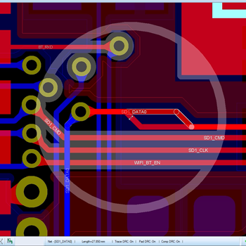
The basic act of route placement is a simple one. The user selects routing mode, clicks on the source pad/track and then the route follows the users mouse movement to the destination when another mouse click completes the route.
Since Proteus knows which net class is being routed it will automatically select the specified track style and via style for the route. It will also ensure that the route obeys all the configured design rules and will intelligently move around obstacles as it follows the mouse during placement.
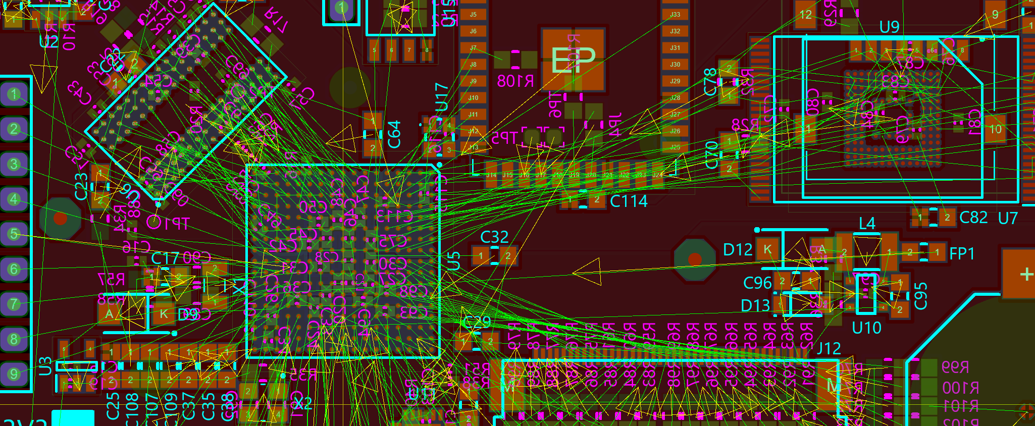
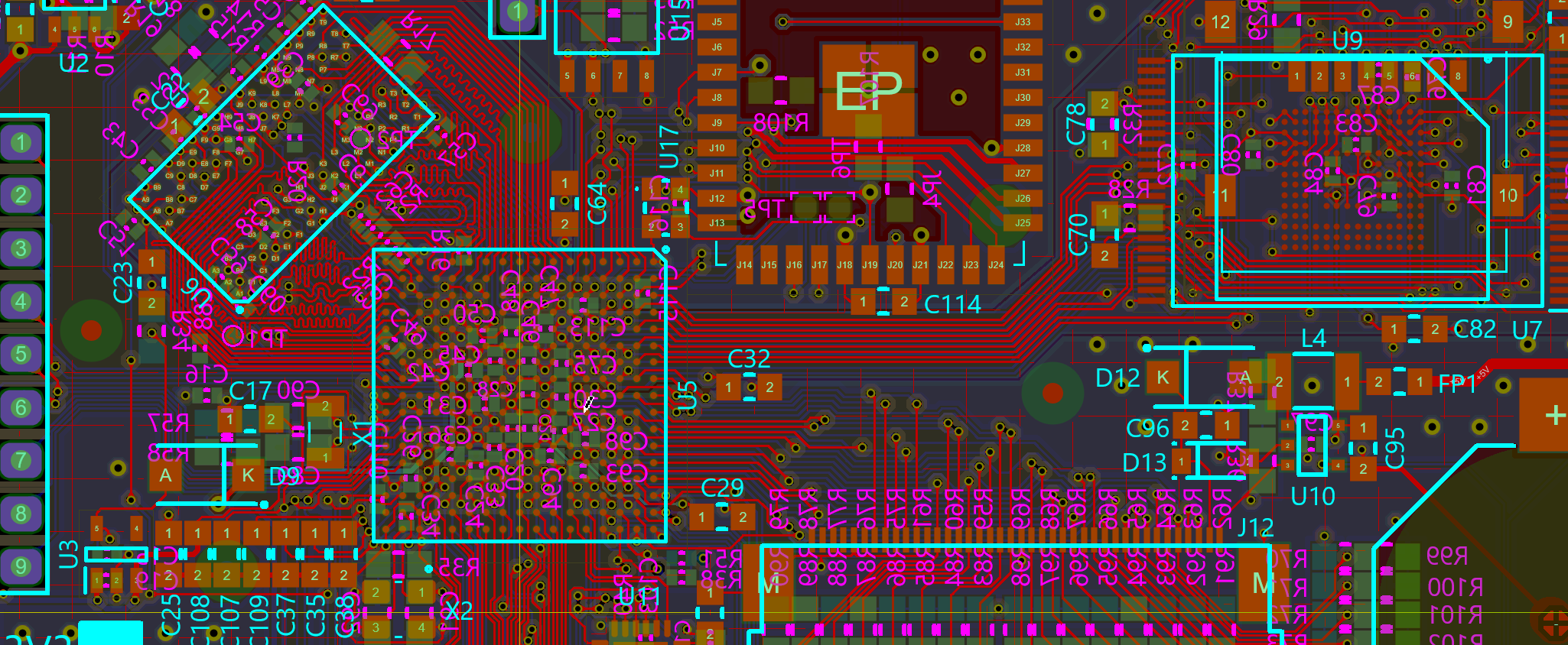
Before and After Slider
Move the slider to compare an unrouted and routed board in Proteus. Push and Shove routing is most helpful with via nudging where escape vias can be jostled to make space for the route being placed or edited.
Push Mode vs FMR Mode
Push and Shove Routing is the default manual routing mode and allows the track being placed to push other tracks (and vias) out of the way to make space. All pushed objects will obey the currently set design rules and you can rewind the pushing operation by moving the mouse backwards.
Follow-Me-Routing (FMR) mode is also a fully design rule aware routing mode but will treat all objects as immovable. It's useful for hugging tracks and where you want total control over all route topology.
You can toggle between modes at any time, including during route placement, via the SHIFT+P keyboard shortcut or in the Route Command Centre.
Route Command Centre
The Route Command Centre is the home for all route placement, editing and configuration options in Proteus. It can be launched from the Tools Menu or, more commonly, via the 'R' keyboard shortcut. Importantly the keyboard shortcut can launch the dialogue form while in the middle of placing or editing a route meaning that you can make changes or adapt the routing modes at any time.
The route commmand centre also provides options for on-the-fly track width changes, design rule aware route editing configuration and the visualisation of design rule clearances (Visual DRC).
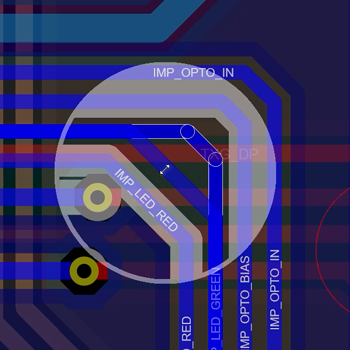
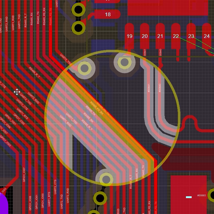
Visual DRC
Visual DRC provides a viewport around the mouse and each object then shows an expansion corresponding to its design rule clearance in an overlay. This instantly lets you see whether the route being placed/edited can move where you want it to go and then take action such as toggling push mode or changing track style to squeeze through a tight gap.
Curved Routing
The process for curved routing is exactly the same as for normal routes except that curved cornering is selected in the route command centre (or toggled with its keyboard shortcut). Since curved mode is activated on a user toggle it can easily be applied to some or all of the route being placed. Curved routed is also fully design rule aware is otherwise identical to linear route placement.
You can also convert corners or mitres after route placement from the route context menu.
Click to Complete
When you start to place a route in Proteus, the software attempts to look ahead and and plots a 'shadow track' showing you how to get to the nearest legal destination without violating design rules. This shadow track will update as the user guides placement towards the intended destination with the mouse. When the shadow track looks right it can be completed automatically by pressing the ENTER key.
This is a huge time-saving feature. It works especially well for simple short distance routes where often the shadow track is correct as soon as you start placement.
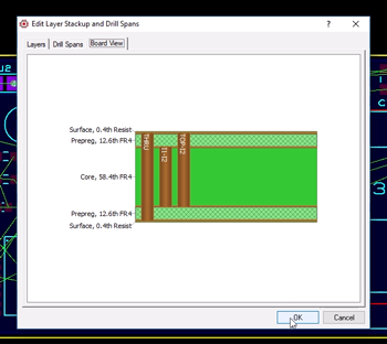
Smart Vias
Vias in Proteus are linked to the specified drill ranges set up by the user in the Layer Stack. This ensures that each blind or buried via hole is legal and manufacturable given the current board configuration. Placement of vias can take place in one of two ways:
1) The user sets up layer pairs to tell Proteus where to go when a via is dropped on a given layer. Double click of the mouse during routing then places the via and routing continues unhindered on the destination layer.
2) The user presses the SPACE bar during route placement to float a via on the end of the mouse and then uses PGUP/PGDOWN to choose the destination layer.
In either case Proteus will use the smallest defined drill pass between source and destination layer to set the via drill range.
Non Functional Pads
A non-functional pad is just a pad in a printed circuit board that is not connected to a track on the layer it is on. These can be removed to either make space and improve routing in tight areas or to reduce unwanted/unnecessary capacitance in sensitive designs.
Despite the name we almost always mean vias rather than component pin holes/pads when we talk about NFPs and the automated tools provided in the software therefore apply to vias only (annular rings in pads are handled by padstacks). In Proteus removing non functional pads from vias is done via a simple menu command on the Edit Menu. The applied range on the layout is by default the entire board but you can gate it to work on a selection. This allows you to select part of the board (e.g. around a BGA) and then apply the NFP removal/restoration only to that area.
The two extremities of the via will always keep their annular rings but all other layers on which there is no connecting track will have their annular ring removed / restored. Depleted vias are automatically restored on the relevant layer should you route to them manually.
- Click and drag to reposition tracks
- Dragging traces maintains angles between segments
- Visual DRC warns of violations when in Guided Editing Mode.
Route Editing
Basic route editing is very simple and works by dragging segments. If you drag a horizontal or vertical segment of the route it will move horizontally or vertically and preserve the angle between adjacent segments. Similarly, if you drag on a diagonal segment it will move such that the angle to the adjacent segments is preserved.
By default, route editing is fully design rule aware and will use the push algorithms to move other tracks and vias as you edit. This makes it easy to tidy up routing and to concertina routes to maximise space on the layout. Push mode can be toggled via keyboard shortcut or in the route command centre. When switched off you edit routes in hug mode with all objects being obstacles and the route being edited stopping at the design rule 'border'. You can also disable DRC awareness completely and the Visual DRC highlighting will warn you of violations but doesn't prevent you moving into illegal positions
Teardrops
Placing teardrops at the connection point between track and pad is often useful in preventing drill breakout during board manufacture. Proteus includes both a global configuration for teardrops and a local override on a particular pad/connection.
Teardrops are fully design rule aware and will not be added in cases where their presence would violate an existing design rule. They will also adapt dynamically if a trace is edited to ensure the best coverage between the connecting track and the pad.
Teardrops on tracks (sometimes known as track tapers) are also fully supported and help avoid sharp changes in track width when necking through tight spaces or to a pad connection.
The ability to add and configure teardrops is part of the advanced feature set and requires Proteus PCB Level 2 or higher.