I learnt about decoupling capacitors with my first real-world microcontroller-based project. The project was a LiPo-Battery Balance Charger, for a 3-cell RC helicopter battery pack. Most of the project was firmware-based; with just a few relays to switch between the cells, and an LCD display and some buttons (there were also a few fat wire-wound resistors for actually discharging cells if needed). I designed and simulated the whole project in Proteus, debugging and tweaking the firmware until it was perfect. Next it was time to physically build the project, and I did this on stripboard. The time came to flip the on switch and see if I had managed to accurately replicate the schematic onto the stripboard, or if any magic smoke was going to escape from the components; to my relief, the display lit up and the text I had previously coded appeared on it. Puzzlingly, all was not quite well however; the firmware was behaving erratically, and restarting randomly. What could be causing that? The answer was that I had failed to add decoupling capacitors into my circuit.
Conceptually (and especially at a schematic level), a power supply simply provides a stable voltage to everything connected to it, and that’s that. In the real world however, things are more complicated. All PCB traces (or wires, in the case of my stripboard project) have both inductance and resistance, and power supplies (such as the 7805 regulator which I was using) do not respond instantaneously to changes in demand. There are also EMI (electromagnetic interference considerations). Integrated circuits, such as microcontrollers, require a stable voltage on their power pins – if this voltage dips or is noisy, then the transistors inside the IC can behave erratically. As the transistors inside the IC switch, and the power which it requires for driving external loads changes, the amount of current which the IC draws varies; if there is a lot of impedance in the lines between the IC and the power supply, then the voltage at the IC will drop whilst it waits for the power-flow to catch up. Picture a dam and a long canal, and a big sluice gate at the end of the canal – if you suddenly open the sluice gate then the water level (voltage) at it will drop rapidly, and it will take a while before water from the dam (power supply) starts bringing it back up again.
 It can take some time for the supply to deliver power.
The solution is to have a smaller dam (capacitor) as close as possible to the sluice gate, and this is what a decoupling capacitor is.
 Small reservoirs of localised power help ensure smooth and responsive power delivery.
Well, that’s decoupling capacitors in a nutshell. Viewed this way, they’re simply small power supplies which are close to the demand and which can help keep things smooth and stable during rapid changes in power requirements. The general idea is to have them as close to the demand as possible, in order to reduce the impedance (inductance, resistance) between them and the IC to as little as possible. From the viewpoint of RF theory, the capacitors shunt high-frequency AC down to ground, providing clean DC to the IC, and this is where the alternative name of “bypass capacitor” comes from.
Many IC and module datasheets will provide recommendations on decoupling capacitors, for example this excerpt from an STM32 datasheet which recommends a 100nF ceramic capacitor next to each pair of power supply pins as well as a larger 4.7uF capacitor nearby
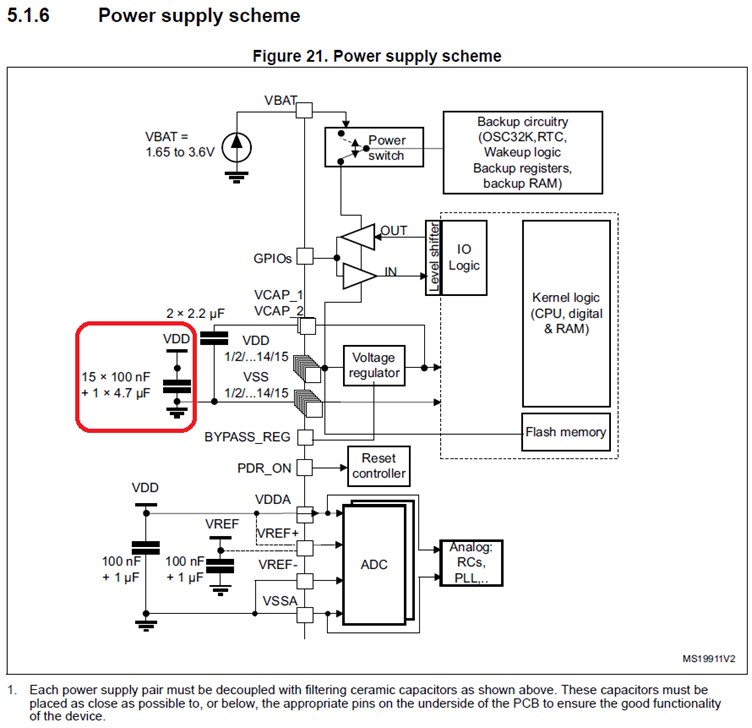 STM32 Recommended Decoupling Capacitors.
Or this excerpt from a GSM module datasheet:
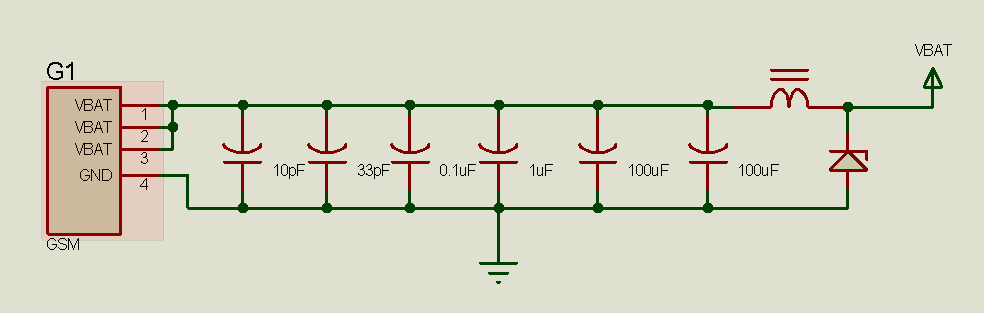 Different decoupling capacitors used with a GSM chip.
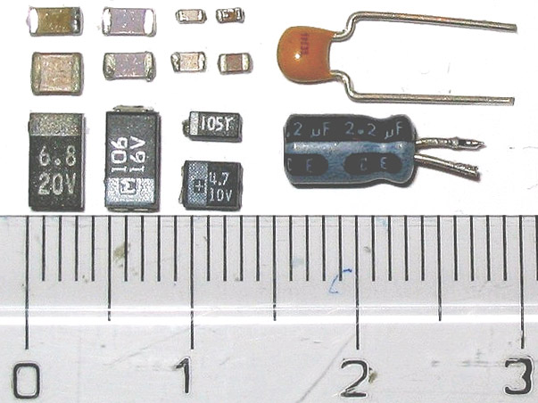
When getting into high-speed design, with GHz clock speeds, things become even more complicated. Capacitors themselves have some inductance and resistance, and the general rule is that physically smaller (not smaller in terms of capacitance) capacitors have lower inductance – so the general rule is to use as physically small a capacitor as possible (e.g. 0402 package is better than 0603), placed as close to the demand as possible. Through-hole capacitors are relatively huge with long leads, and are out of the question at this point. In the excerpt from the GSM module datasheet above, a range of different-valued capacitors are recommended – the idea being that the smaller capacitors react faster, whilst the larger capacitors react more slowly but have greater capacity. There is debate regarding how relevant this technique is however if the package sizes (and therefore lead inductances) of the capacitors are the same, as the larger capacitors with the same lead inductance should react just as quickly as smaller capacitors of the same package. Having capacitors of different values in parallel can also change the overall impedance characteristics, creating different resonance and antiresonance peaks. If in doubt, then follow the manufacturer recommendations.
If it is known what frequency of noise the capacitor will see, then the idea is to pick a capacitor with a series self-resonant frequency close to the frequency of the noise (dip point in the graphs below):
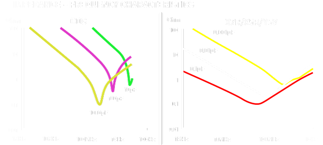 Impedance-Frequency Characteristic Graphs.
At this frequency, the capacitor will have the lowest impedance and will best “bypass” the noise to ground (protecting the IC from it).
For those not yet handling the complexity of very high-speed designs however, following the manufacturer recommendations (which usually amounts to placing a 100nF capacitor as close to the IC power pins as practical) will result in stable operation.
All content Copyright Labcenter Electronics Ltd. 2026. Please acknowledge Labcenter copyright on any translation and provide a link to the source content on www.labcenter.com with any usage.Get our articles in your inbox
Never miss a blog article with our mailchimp emails