As signal speeds get faster and operating currents lower, the integrity of the signal becomes an increasingly necessary consideration during PCB Design. In particular, the transit time of signals often needs to be synchronized by matching the copper length of the traces on the PCB. The basic idea of this length matching is that the shorter trace follows a detour or meander in order to lengthen it to match the length of the longer trace.
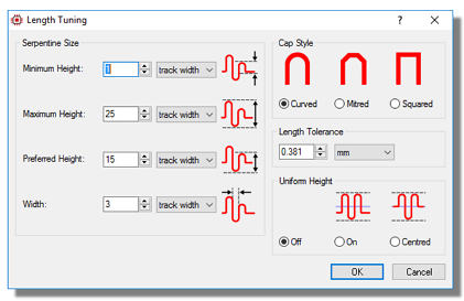 Configuring the meander or serpentine style in the Proteus Design Suite
This post provides a broad overview of some different length matching (sometimes called net tuning) situations and looks at how your EDA tool can help you with high speed routing. Differential pairs are outside of this topic and will be covered in a separate post.
Equalizing a set of routes
This is probably the most common situation and is where you want to make the length of a number of traces the same. This is commonly known as creating a matchgroup consisting of those tracks. A matchgroup is simply a container for a set of routes that have been successfully length matched. It includes the target length, the tolerance, the serpentine configuration and a list of the routes that belong to it. You can have as many matchgroups as you need in a design, each with different serpentine configurations and tolerances.
Different EDA Tools will manage matchgroups in different ways but almost all can do the length matching job for you. In the Proteus Design Suite you simply select all the target tracks and invoke the length match command with the matchgroup being created automatically based on your selection.
Matching to a target length
In this situation instead of matching the length of the tracks with respect to the longest track in the selection, the requirement is to match the length of the tracks to an absolute value by inputting the target length. This is otherwise identical to matching a set of tracks against each other but, depending on your tool of choice, may be implemented in a different way. In some EDA tools the matchgroup is defined first along with the target length and then you place the routes with an automatic serpentine until you are compliant. In other tools, including Proteus, you first route the traces normally and then you select and input the target length. Any necessary serpentine routing will then automatically take place on the routed tracks. In either case you should then be able to select the serpentine segments and freely move them around to your preferred location on the track.
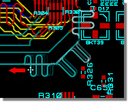 Dragging Serpentine Segments into position
Complex Length Matching
So far, in all of the length matching we’ve covered, all of the tracks belong to a single matchgroup. However, it is sometimes unavoidable that one section of track belongs to more than one matchgroup. A good example of this is the fly-by routing of the CMD/ADDR lines with DDR3. As an example, consider the following topology:
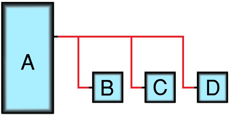 Simplified fly-by configuration example.
AB, AC and AD are all critical signals and will need to be matched to specific lengths. It is inevitable however that some track segments will be included in multiple matchgroups.
 The horizontal sections of (blue and green) track are included in several matchgroups.
Again, different EDA tools will handle this problem in different ways. One common rule of thumb for the user however is to route and length match the shortest segment first and work your way towards the longest segment. In our example above this would mean routing AB first, since AB has less space to serpentine and it is more likely to require the common trace section for lengthening.
Non-Etched Lengths
If the length matched routes need to pass up and down the PCB then it will be important to consider the length of the drill holes so that this distance is added to the total length. Almost always, this layer thickness information is entered during the setup of the layer stackup and is then used automatically by the software during length matching.
Sometimes, the signal speeds are so high and the timing budgets so tight that the signal delay inside the chip can be relevant. In this case you want to add an internal length to the length matching algorithm. With Proteus Design Suite this takes the form of a property that you add to the footprint as a comma separated pin name, length listing.The eventual length matching calculation therefore is something like:
<etched copper length> + <internal lengths> + <drill depth x num holes>
and will be matched inside your specified tolerance.
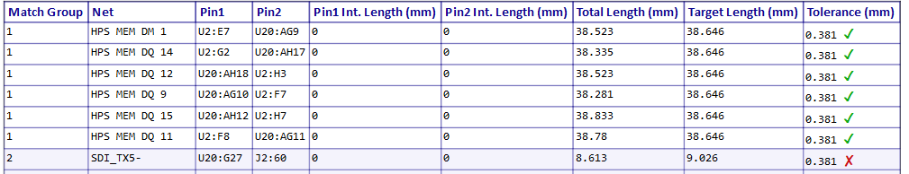
Reporting
On a complex board there can be a good number of matchgroups and therefore a large number of length matched routes. Since the layout of such a PCB is in itself a complex task you’ll want to be sure that all of your length matches remain inside tolerance before sending the board for prototyping.
Typically, you’ll find a length match report or a net tuning compliance report available in your software package which will list all of the routes in a matchgroup along with their current status.
Often you can also select and browse matchgroups on the layout using the connectivity highlights feature.
Summary
Length matching routes has moved from a niche technique on cutting edge design to a mainstream requirement in PCB layout. Fortunately, there is a lot your PCB software package can do to help make life easier for you when faced with high speed design requirements. If you’re interested in learning more about how length matching is supported in the Proteus Design Suite you’ll find a short video tutorial via the link below:
All content Copyright Labcenter Electronics Ltd. 2026. Please acknowledge Labcenter copyright on any translation and provide a link to the source content on www.labcenter.com with any usage.Get our articles in your inbox
Never miss a blog article with our mailchimp emails