Introduction
Despite being one of the earliest forms of display technology - having a history dating back to the beginning of the 20th century - 7-segment displays are still very much in use and relevant today, as a low-cost display solution
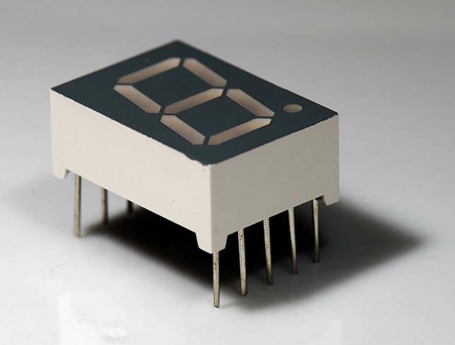
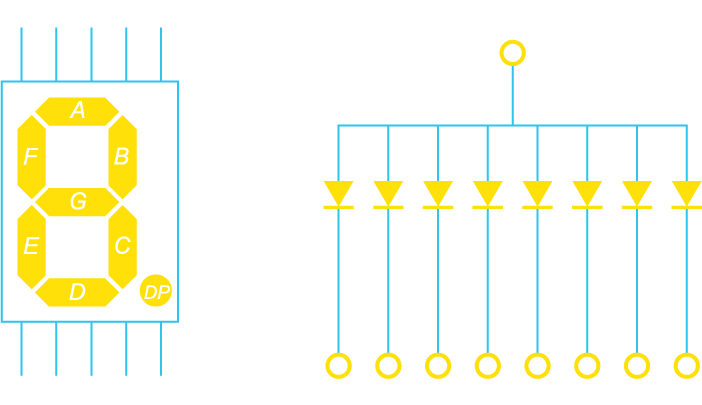
As indicated by the name, 7-segment displays consist of 7 individual segments; these segments can be turned on and off individually, combining to produce numbers (and letters). There is often also a decimal point (8th segment), and there are also variants with other additional segments, however 7-segment display is generally the colloquial term used for this technology. The colloquial term also generally refers to displays where the segments are each illuminated by an LED, however various other optical and mechanical forms of 7-segment displays also exist. In this article however we will be referring to the colloquial, LED-illuminated displays.
Anatomy of a Display
7-segment displays usually have 1 pin for each LED, and then 1 pin connected to all the LED cathodes (common cathode) or anodes (common anode). Connecting all of the LED cathodes or anodes to a single pin obviously saves on the number of pins needed, and still allows each LED segment to be driven individually using the pin on its other end.
7-segment displays can also be arrayed next to each other to create multi-digit displays.
Driving a Display
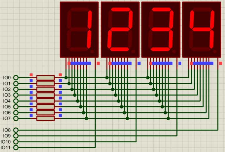
Connecting each segment LED to its own GPIO pin on a microcontroller will quickly start to require a very large number of pins as the number of segments increase, however there is a technique for driving the segments which uses only 2 additional pins to drive 2 digits and only 1 additional pin per digit thereafter.
By connecting each of the corresponding segment LEDs in each digit to the same GPIO pin, and then connecting the common cathode or common anode to another free GPIO pin, each digit can be driven individually by the microcontroller – the segment GPIO pins control the segments, and the anode/cathode pins control which digit is selected. Of course, this means that only one digit can be illuminated at any given time – but thanks to persistence-of-vision, if we continuously refresh (turn on the LED segments in) each individual digit fast enough – cycling from digit to digit – then it will appear to the naked eye that the entire display is being illuminated at once!
Persistence-of-vision is the same reason that a movie consisting of 24 individual still frames (pictures) per second appears smooth to us rather than jerky, or why fast-moving objects appear blurry – things start to blend together if they change fast enough.
One drawback to this method however is that the brightness of the LEDs will be reduced in proportion to how many digits there are. 2 digits will mean that each digit is on for only half the time, and will therefore only appear half as bright; 3 digits will appear 1/3rd as bright, 4 digits ¼ as bright, and so on. This is the same as how LEDs are dimmed with pulse-width modulation. This should be taken into account when designing the system, and corresponding brightness specification displays chosen accordingly.
On the software side, cycling of the display digits can be done from a timer interrupt, an RTOS thread, or any other mechanism with a reliable timing between executions.
Other methods for driving 7-segment displays include using shift registers (such as the 74HC595) or dedicated driver ICs (such as the MAX6954); these methods use fewer GPIOs, however require additional external components.
Proteus includes a number of 7-segment display models which correctly model persistence-of-vision, and can therefore be driven using the technique described in this article. You'll find examples using PICs, ARM, 8051 and Arduino micro-controllers, all of which you can simulate in the demo version.
All content Copyright Labcenter Electronics Ltd. 2026. Please acknowledge Labcenter copyright on any translation and provide a link to the source content on www.labcenter.com with any usage.Get our articles in your inbox
Never miss a blog article with our mailchimp emails
Advanced Simulation
Learn more about our built in graphing and advanced simulation features. Harness the mixed-mode simulation engine in Proteus to quickly test your analogue or digital circuitry directly on the schematic.
 Ask An Expert
Have a Question? Ask one of Labcenters' expert technical team directly.