Introduction
Pulse-width modulation (or PWM for short) is a simple concept which has many applications. Let's take a look at a square wave.

The waveform has a certain frequency. The frequency and period of the waveform are the inverse of each other, i.e. Frequency = 1/Period and Period = 1/Frequency. A period of 1s means a frequency of 1Hz. A period of 0.1s means a frequency of 10Hz, and a period of 10s means a frequency of 0.1Hz.
Note that the signal is entirely digital, in that it is either on/high, or off/low. This is different from – for example – a sine wave, which is analogue and transitions smoothly throughout the waverform (see our article on analogue and digital signals).
Note also that, for a square wave, the signal is on for half of the time, and off for half of the time.

The on part of the waveform is called the Duty Cycle – it is the proportion of time for which the signal is providing power / doing work / on duty. For a square wave this is 50% of the time, meaning that the signal has a 50% duty cycle; i.e. if the period was 1s (frequency was 1Hz), then the signal would be on for 0.5s and off for 0.5s.
The positive or on part of the waveform can also be thought of as a pulse of energy. By modifying the width of the pulse (the duty cycle), we can change the proportional amount of energy in the waveform.

From this comes the term Pulse-Width Modulation (modifying the width of the pulse).
Main Uses of PWM
Pulse-width modulation (hereafter referred to as PWM for short) is one way in which a digital system can generate an analogue output (by passing the PWM signal through some additional circuitry and/or mechanical system). Some examples of applications for PWM are:
- A PWM signal can be used to generate an analogue voltage by passing the signal through a low-pass filter.
- PWM can be used to proportionally control the speed of a DC motor.
- PWM is used to set the position of some types of servo motors.
- PWM can be used to control the amount of heat generated by a heating element.
- PWM is used in buck and boost converters to convert an input voltage down to a lower voltage or up to a higher voltage (see our Buck and Boost Converter articles).
- PWM can be used to control the [apparent] brightness of a lightbulb or LED.
- ... and many, many more.
 DC Motor.
 Servo Motor.
In some cases the output is an electrical voltage or current, in other cases it is a physical quantity such as force / position / heat / brightness, but in all cases the output can be scaled smoothly between the maximum of completely on and the minimum of completely off by using the PWM.
PWM to Analogue Signal
Let’s take a look at the case of converting a PWM signal to an analogue voltage. For this we need a low-pass filter (see our filters article).

The 5V digital PWM is converted to a 2.5V analogue output (50%of 5V = 2.5V).
All of these simple experiments can be quickly repeated in Proteus with the advanced simulation features module.
Smaller values of R (Resistor) or C (Capacitor) will result in a faster response to changes in input, but more jitter on the output (and vice versa).

Changing the duty cycle will change the output voltage. A 20% duty cycle for example will result in an output of 1V (20% of 5V = 1V):

Conversely, an 80% duty cycle will result in an output of 4V (80% of 5V = 4V):

Increasing the frequency of the PWM will also decrease the jitter of the output:

Note that this in turn means that relatively lower Resistor and/or Capacitor values can be used and therefore relatively quicker responses obtained to changes in input. This is a general rule for PWM: The higher the PWM frequency, the smoother and more responsive the output can be.
Regarding responsiveness however, just remember that in order to increase responsiveness the smoothing element in the system (resistor-capacitor low-pass filter in the examples above) must be made smaller. Alternatively, the input power level (input waveform voltage in the examples above) should be increased. In a mechanical system, the smoothing element of the system may be the inertia (mass) of the system – more on that to follow.
There are always upper limits to how high the PWM frequency can be – this may be limited by the clock frequency of the digital system generating the PWM, or by how quickly the switching element(s) in the output system can respond – a relay may take a few ms to switch, or a valve may take some time to open/close, for example.
As covered in our passive filters article, an Inductor-Resistor low-pass filter can also be used:

Resistor-Capacitor filters are generally however preferred for this particular sort of application, due to the lower frequencies / component sizes required.
Embedded PWM
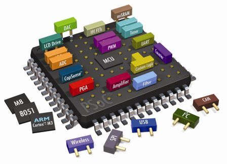
Most modern microcontrollers have built-in PWM peripherals which can generate PWM outputs within a certain range of frequencies and resolutions. If frequencies are required which are lower than those which can be generated by the PWM peripheral, then this can be done by using a timer interrupt and manually setting the pin high and low.
In Arduino, the analogWrite() function directly generates a PWM output:

Head over to the Sample Design Browser to quickly find a set of ready-made embedded simulation sample projects that are included with the Proteus demo version.
PWM with Mechanical Elements
For mechanical systems, the smoothing element of the system is often the inertia of the system – meaning how quickly the system reacts to a change in input. This is covered in our Buck and Boost Converter articles using the concepts of a Flywheel / Merry-Go-Round.

Imagine we added a water-jet to a merry-go-round, and that we could open and close that water-jet with a solenoid valve.
If we open the valve then the merry-go-round spins faster, if we close the valve then the merry-go-round will naturally slow down again due to resistance from the air and bearings.
According to Newton’s 2nd law of motion, Acceleration = Force / Mass. If we assume that the the force is constant (with PWM the force is generally assumed to be constant, since the voltage of the waveform is constant – we won’t get more complicated than that for now, we’ll assume that the water pressure is constant), then we can see that the acceleration is purely dependant on the mass (inertia). The speed at which the merry-go-round spins will be given by the formula Speed = Acceleration x Time. From these formulas we can see that the speed is directly proportional to the force, and if the force is only applied for 50% of the time (50% duty cycle) then the speed will also be 50% of what it would be if the force were applied constantly. 10% duty cycle would mean 10% speed, 90% duty cycle would mean 90% speed, and so on. From this we can see that we can generate an analogue output (speed) from a digital input (controlling the water jet as either completely on or completely off) by varying the duty cycle.
There are some aspects which we haven’t looked at in detail, such as the specifics of the resistance forces acting in the opposite direction to the water jet and how the distance of the water jet from the center will affect things, but what we have looked at is enough to cover the PWM principle. We can note that the maximum frequency of the PWM will be limited by how fast the solenoid controlling the water-jet can open and close, and also that the jitter in the system (for a given frequency) will depend on the mass of the merry-go-round – this is because the merry-go-round will always be either accelerating (water-jet open) or deaccelerating (air / bearing resistance) but the higher the mass the less the acceleration (change in speed) will be due to those forces (less jitter).
The same principles apply to a DC motor driven around by magnetic fields (rather than by a water-jet), a heating element in a water-tank, a DC light-bulb, and so on. The apparent dimming of an LED by PWM is due to the optical frame-rate of our eyes (persistence of vision), however that is a subject for another article!
Summary
Overall, the principle of PWM is very simple – converting a digital input to an analogue output. The variables in the system are the force (voltage), frequency, duty-cycle, and inertia of the smoothing element; and the tuning limits of these vary per application.
All content Copyright Labcenter Electronics Ltd. 2026. Please acknowledge Labcenter copyright on any translation and provide a link to the source content on www.labcenter.com with any usage.Get our articles in your inbox
Never miss a blog article with our mailchimp emails
Advanced Simulation
Learn more about our built in graphing and advanced simulation features. Harness the mixed-mode simulation engine in Proteus to quickly test your analogue or digital circuitry directly on the schematic.
 Ask An Expert
Have a Question? Ask one of Labcenters' expert technical team directly.