

Published 6 September 2026
Introduction
The first three articles in this series took CAN apart: the frame, the faults and the attacks. This one puts it back together and asks a simpler question. In a working car, what do the drivetrain's controllers actually say to each other? Not in the abstract, but message by message: which node owns the engine speed, where the speedometer gets its number from, what a gearbox announces when it changes gear, and why the fuel level and the fuel consumption come from two different boxes. Knowing the answers turns an analyser full of hex into a description of a car, and it is the knowledge you need before you add an ECU of your own to the bus.
The examples run on the Proteus Automotive CAN simulation, mainly its powertrain sample, which puts an engine ECU, a transmission controller, a fuel system and an instrument panel on one bus with the analyser, and its chassis sample, which adds the vehicle dynamics, steering and braking nodes along with the parking brake, power steering, airbag, tyre pressure and suspension modules. The nodes are behavioural: each one transmits the messages a real ECU of its kind would transmit, decoded by the same database file, and reacts to the messages it would consume. They do not simulate the mechanics behind those messages, and this article is careful to say where the real car does something the model leaves to you. The message layouts, scalings and identifiers are all real, and are quoted from the database the samples ship with. It assumes Anatomy of a CAN Transmission, in particular the section on signals and the DBC.
Who Talks on the Powertrain Bus
A drivetrain bus has a small number of transmitters and a larger number of listeners. The engine ECU is the busiest source: engine speed, throttle, load and temperatures, a second message of sensor data, a fuel economy message and a periodic report of its diagnostic state. The transmission controller (TCM) reports the selected gear, the shift in progress and the torque it is passing on, and reads the engine speed to do so. The fuel system reports the tank. On the chassis side, the vehicle dynamics node owns vehicle and wheel speeds, the steering angle sensor owns the steering angle, and the ABS and stability controller consumes both and reports braking and stability status. The instrument panel transmits no broadcast data of its own; it reads everything it displays off the bus, and like every ECU it answers diagnostic requests. And the scan tool, which the diagnostics and showcase samples include, speaks only when spoken to, on the diagnostic identifiers.
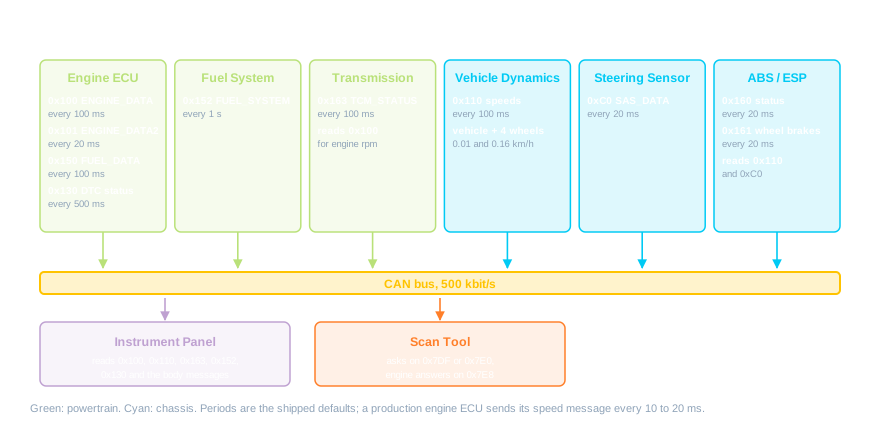
Every signal has exactly one owner, and that rule holds the whole thing together. The engine speed is the engine ECU's to send and nobody else's; the fuel level belongs to the fuel system, not the engine; vehicle speed belongs to the node that measures it. When a signal needs to move house, as the fuel level did in the design of this simulation, it moves out of one message and into another rather than appearing in both. Two nodes transmitting the same signal is a fault waiting to happen, as the earlier articles showed, and a database in which a signal appears under two identifiers is a design smell worth chasing down. The sample database has one, and it is instructive: it still defines a STEERING_GEAR message at 0x120 carrying steering angle and gear, both of which moved to their proper owners, the steering sensor and the gearbox, and nothing transmits 0x120 any more. Databases outlive their messages, and the analyser, not the database, tells you what is really on the bus.
The Engine's Messages
The engine's main message is the one every other article in this series has used as its example, and here it is in full. ENGINE_DATA, identifier 0x100, eight bytes: engine speed in the first two bytes at 0.25 rpm per bit, then throttle position and engine load at 0.4 percent per bit each, then coolant, oil and intake air temperatures as single bytes offset by minus 40 so that 0 means minus 40 degrees C and 255 means 215, and finally an engine status byte that enumerates Off, Cranking, Running and Stalling. Every consumer on the bus that cares about the engine reads this one message. In the sample it is sent every 100 ms; a production engine ECU sends its speed and torque message every 10 or 20 ms, because the gearbox and the stability controller need it that often.
A second message, ENGINE_DATA2 at 0x101, carries the sensor suite that a technician rather than another ECU is interested in: mass air flow, manifold pressure, boost, the two lambda readings from before and after the catalyst, ignition timing, a knock counter and injector pulse width, packed into the same eight bytes with the scalings and offsets that make them fit. A third, FUEL_DATA at 0x150, carries fuel consumed and instantaneous consumption (in the sample both read zero; the layout rather than the value is the point), and a fourth, ENGINE_DTC_STATUS at 0x130 every half second, carries the malfunction indicator state, the number of stored trouble codes and the most recent one, which is how the instrument panel knows to light the engine warning lamp without asking. In the simulation the engine ECU can be driven by hand from its window or set to an idle, cruise or sweep profile; the sweep runs the engine from 800 to 7,000 rpm and back every ten seconds, which is a convenient way to watch every consumer follow it.

Speed Comes From the Wheels
A common surprise is where the speedometer's number comes from. It is not the engine. Vehicle speed is measured at the wheels, by the same wheel speed sensors the anti-lock braking system uses, and in most production cars the ABS or stability control module is the node that owns and broadcasts it. Everybody else, the instrument panel, the engine ECU, the gearbox, the body computer that locks the doors once the car is moving at 10 or 15 km/h, reads it from the bus. In the simulation that role is split between two chassis nodes: the vehicle dynamics node owns VEHICLE_DYNAMICS at 0x110, with vehicle speed at 0.01 km/h per bit and four wheel speeds at 0.16 km/h per bit, sent every 100 ms in the sample; the ABS and stability controller consumes that and the steering sensor's angle and reports what it is doing about them.
That report shows how a safety controller talks: ABS_ESP_STATUS at 0x160, every 20 ms, carries flags for ABS, stability, traction and brake-force distribution intervention, a per-wheel brake-active bit, yaw rate at 0.1 degrees per second with an offset of minus 250, lateral acceleration at a thousandth of a g with an offset of minus 2, master cylinder pressure, and a rolling counter and checksum of the kind article 2 recommended, so that a consumer can tell a live frame from a stale one. A companion message, 0x161, carries the four brake pressures. The controller's logic in the simulation is deliberately simple, estimating yaw from the difference between left and right wheel speeds and comparing it with what the steering angle and speed imply, and firing a per-wheel brake when they disagree; a real controller's algorithms are the manufacturer's crown jewels. But the messages it produces, and the reason a real controller needs wheel speeds and steering angle every 10 to 20 ms to produce them, are the real thing. In the sample the wheel speeds arrive every 100 ms, so the controller's 20 ms loop is working on data that refreshes ten times a second.

The Gearbox
The transmission controller's message, TCM_STATUS at 0x163 every 100 ms, is a good example of a message that mixes state, transient and measurement. The selected gear is an enumeration: P, R, N, D and six manual positions. A shift state field reports Idle, Upshift, Downshift or Fault, and in the simulation a gear change raises it for about 600 ms and then lets it fall back, which is exactly the kind of transient a consumer has to be written to catch rather than poll for. A target gear field says where the shift is going; in a real gearbox it leads the selected gear during the shift, while in the model the two step together and only the shift state is transient. Torque converter lock-up is a flag, engaged in the model only once a forward gear is selected and the shift has settled. Output torque is a 16-bit value with an offset of minus 500 Nm so that it can go negative on the overrun, gear ratio is scaled at 0.04 per bit, and the transmission fluid temperature uses the same minus 40 offset as the engine's temperatures.
The TCM is also the clearest consumer on the powertrain bus. It reads ENGINE_DATA for engine speed, uses it for an illustrative shift-logic readout and to derive its output torque from the gear ratio, and if the engine message stops for a second and a half it does what article 2 described: it logs its own lost-communication code for the engine, and carries on with the last value it saw. In a production car the coupling runs the other way too. During an upshift the gearbox asks the engine to cut torque for a few hundred milliseconds so that the shift is smooth, and the engine ECU honours the request; that torque intervention is a message from the TCM to the engine, and it is one of the reasons the two talk at 10 ms rather than 100. The simulation does not model the request, and writing a node that does is a natural exercise for the student ECU.

Fuel: Two Owners, Two Messages
Fuel is the tidiest illustration of the one-owner rule. How much fuel is in the tank is known by the sender unit in the tank, so the fuel system node owns FUEL_SYSTEM at 0x152: the raw level and a filtered level, a low-fuel warning, the pump status, an estimated range and the fuel temperature. How much fuel the engine is using is known only by the engine, which is metering it through the injectors, so the engine owns FUEL_DATA at 0x150 with the consumed and instantaneous figures. The instrument panel reads the fuel system message for its gauge and low-fuel lamp; the economy figures are there for a trip computer to consume.
The fuel message is sent once a second, the slowest message on the bus, because fuel level changes slowly and nothing safety-relevant depends on it; sending it faster would be bus load for nothing. It also carries the level twice, raw and filtered. A fuel sender sloshes as the car corners and brakes, and a gauge driven from the raw reading would swing with it, so the node applies a slow first-order filter and sends both, leaving the consumer to choose. The low-fuel warning has hysteresis for the same reason: it comes on at one level and goes off at a higher one, so that a car parked on a slope does not blink its warning lamp at the driver.
Timing Classes and Identifiers
Put the periods of the powertrain and chassis nodes together, as they are in the showcase sample, and a structure appears. The fast class, at 20 ms in the sample and 10 to 20 ms in a production car, holds the messages that a control loop somewhere depends on: engine sensors, steering angle, the two braking messages. The medium class, at 100 ms, holds state that changes on a human timescale: engine data in the sample, vehicle speed, gear, fuel economy. The slow class, at half a second or a second, holds status: diagnostic state, fuel level. Each class is a design decision about latency and bus load, and getting a message into the wrong class is a real fault, the off-rate node of article 2.
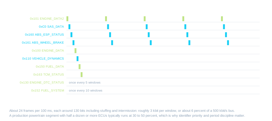
The identifiers follow the same logic from the other direction. Since the lowest identifier wins arbitration, the numbering is a priority list: the steering angle at 0xC0 and the airbag module at 0xD0 sit below the engine at 0x100, the chassis and powertrain messages between 0x110 and 0x164 sit below the body messages at 0x200 and above, and the diagnostic request and response identifiers from 0x7DF upwards sit near the bottom, because a scan tool's question can always wait. With the powertrain and chassis nodes together, all of this adds up to a couple of hundred frames a second, well under 10 percent of a 500 kbit/s bus. A production powertrain segment carrying half a dozen or more ECUs, on a car with dozens, runs at 30 to 50 percent, which is where the discipline starts to matter.

Two Views of the Same Engine
Everything so far has been broadcast traffic: nodes sending what they know, on a schedule, to whoever is listening. A vehicle bus carries a second kind of conversation alongside it. Diagnostics are request and response. A scan tool sends a request on the functional identifier 0x7DF, which every emissions-related ECU listens to, or on a physical identifier 0x7E0 to 0x7E7 aimed at one of them, and the ECU replies on 0x7E8 to 0x7EF. The requests and replies are wrapped in a one-byte transport header giving the length, so a request for engine speed is the frame 02 01 0C: two bytes follow, Mode 01 (live data), parameter 0x0C. The engine replies 04 41 0C 17 70: four bytes follow, Mode 01 positive response, parameter 0x0C, and the value 0x1770, which the standard says to divide by four, giving 1500 rpm.
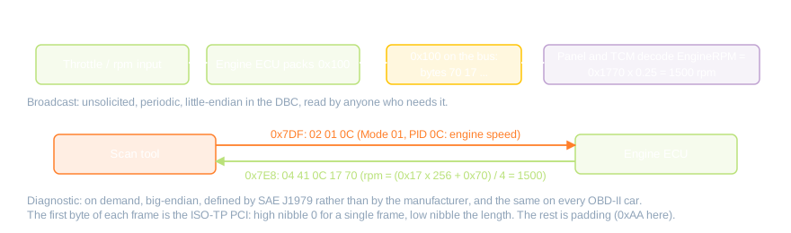
The two routes carry the same number and differ in every other respect. The broadcast is unsolicited, periodic, laid out however the manufacturer chose, and readable only with the manufacturer's database. The diagnostic reply is on demand and laid out by SAE J1979, the same on every car with OBD-II, which is every car sold in the United States since 1996 and in Europe since the early 2000s: engine speed is parameter 0x0C divided by four everywhere, and since 2008 the CAN identifiers that carry it have been standard too. That is why a garage's scan tool works on any make while a manufacturer's own tool reads far more. In the simulation the engine ECU answers the standard live-data requests, reports and clears trouble codes, returns a freeze frame of the conditions when a code was set, and gives its VIN, so the scan tool node sees it exactly as it would see a car. Before you try it, note that a request on the functional identifier is answered by every emissions ECU, and the sample engine node also plays a second, virtual transmission ECU that replies on 0x7E9 with an engine speed of zero, because a gearbox has no crank sensor. Two replies to one question is exactly what a real car does. Address the engine physically on 0x7E0 and you get its answer alone. Watch both routes on the analyser at once and the lesson is complete: the same engine speed, in the same simulation, expressed two ways for two audiences.

Following a Chain Across the Bus
The best way to learn a bus is to follow one quantity along it. Start at the engine window and raise the throttle. On the analyser, the raw bytes of 0x100 change and EngineRPM climbs on the Signals tab. Within one 100 ms period the TCM window's shift-logic readout and output torque follow, because it has decoded the same frame, and the instrument panel's rev counter sweeps, because it has too. Three nodes, one message, no wiring between them. Now use the analyser's error injection from article 2 or a fault property to silence the engine. The bytes stop. A second and a half later the TCM logs its lost-communication code, the panel shows its warning, and the scan tool, asked for stored codes, returns U0100 from both of them. The chain has been read forwards and then broken, and every link showed itself on the bus.
In the simulation the engine speed and the vehicle speed are separate inputs: raising the throttle does not make the car go faster, because the nodes model messages, not mechanics. In a real car the two are tied together by the gear ratio and the final drive, and a mismatch between them is how a stability controller detects wheel spin. What this means is that writing that tie is a good first ECU of your own, on the showcase sample, which has the engine, the gearbox and the vehicle dynamics node together. Read engine speed from 0x100 and the gear from 0x163, compute the road speed the drivetrain implies, compare it with the wheel speeds on 0x110, and transmit a slip figure on an identifier of your choosing. Every input is already on the bus, the database tells you how to decode each one, and the analyser will show you whether your frame is right. That is the whole discipline of automotive networking in one afternoon.
See how CAN nodes are added, wired and configured on a Proteus schematic in our CAN Bus Introduction video.
Summary
A drivetrain bus is a small number of owners and a large number of readers. The engine owns its speed, load and temperatures and sends them fast; the gearbox owns the gear and the shift and reads the engine to do its job; the fuel system owns the tank and the engine owns the consumption; and the speed everyone displays comes from the wheels, through the braking controller, not from the engine at all. Periods fall into fast, medium and slow classes that reflect what depends on each message, identifiers are allotted as a priority list, and the diagnostic identifiers at the bottom carry a second, standardised conversation for the garage. Learn to read one bus this way and the next one, on a different car with a different database, will look familiar within an hour.
The powertrain and chassis samples in the Proteus Automotive CAN simulation contain every node described here, decoded by the vehicle.dbc database that ships with them, with the CAN Bus Analyser's Signals, Frames and statistics views; add the Scan Tool part, or open the diagnostics sample, to read the second route to the engine. Any Proteus VSM processor can be added to the same bus to become the student ECU described in the last section.All content Copyright Labcenter Electronics Ltd. 2026. Please acknowledge Labcenter copyright on any translation and provide a link to the source content on www.labcenter.com with any usage.