
CAN Bus & Automotive Networking
CAN bus turns up in just about every automotive and embedded course, and it is a genuinely awkward thing to teach well. A worthwhile exercise needs several nodes talking to each other, and kitting out a whole class with ECUs, transceivers, wiring and analysers is expensive, fragile and slow to set up. Too often the lab time goes on chasing bad connectors instead of writing firmware, and the students never get to see a properly busy bus.
Proteus VSM takes a different route. Students write real firmware on whatever processor family the course already uses, a PIC, AVR or 8051, an Arduino or an ARM in C, or MicroPython on a pyboard, and run it against a complete simulated vehicle network right there in the schematic. The idea clicks quickly: the brake pedal is not wired to the lamp, it just sets a bit in a broadcast message, and another ECU decides to light the lamp.
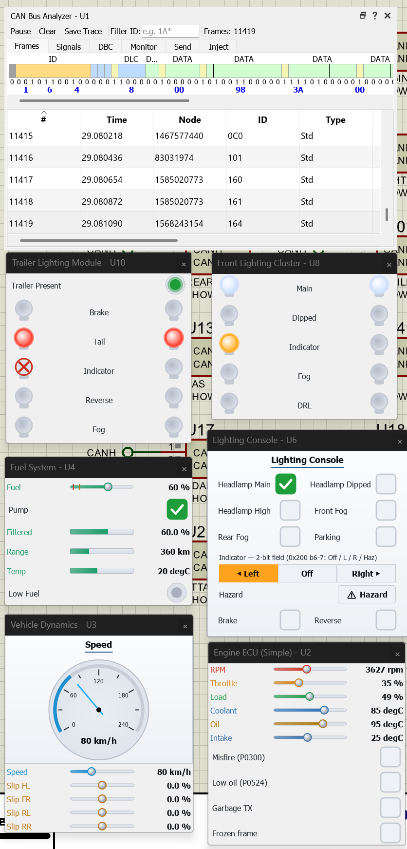
What makes it work is the set of behavioural car-part nodes, more than twenty of them covering the whole vehicle. The Instrument Cluster, Engine ECU, Body Control Module, Vehicle Dynamics and the front and rear Lighting Clusters are typical examples: each drops onto the schematic as a single component with CAN pins and a live popup window, where the gauges sweep, the lamps come on and sliders let you inject stimulus. Because these nodes are behavioural models rather than extra microcontrollers, the whole network simulates at the cost of a single MCU.
The student's own MCU then joins the same bus, and the nice part is that it does not need a CAN peripheral of its own to do it. A device with on-chip CAN, like the pyboard or an STM32F103, drives the bus directly, but any microcontroller in the Proteus library can take part just as well, a PIC, an AVR, an 8051 or a Cortex-M0 included, simply by talking over SPI to a stand-alone CAN controller. Proteus supplies models for the parts you need to do this: the MCP2515 controller for classical CAN and the MCP2518FD for CAN FD. One more part finishes the job, and it is modelled too. Every node needs a CAN transceiver, such as the MCP2551, TJA1050 or SN65HVD230, sitting between the controller and the wire to turn the logic-level signals into the CANH and CANL pair that forms the physical bus. Some devices roll the controller and transceiver into a single chip. The practical upshot is that a CAN course is not limited to the handful of parts that happen to have a controller built in, it can use almost any processor Proteus simulates.
Then there is the CAN Bus Analyser, which is where the bus becomes something you can actually read. It captures and timestamps every frame, decodes it by name from the loaded DBC file, and opens any frame field by field, from its identifier and data through to the CRC. It will also transmit frames on demand, report each node's error state, inject faults to push a node into bus-off, and export Vector and PEAK trace files. There is a good library of ready-made sample designs as well, covering message reception, lighting control, gateways that bridge two bus segments, fault recovery and security. Security gets a system of its own: a rogue node can spoof, replay or flood the bus, a passive intrusion detector catches it, and authenticated messaging with seed-and-key access control shows the defence, all safely on a simulated bus. Every student runs the same lab at home, with nothing to wire up and nothing to break.
Serial Interconnect: SPI, I²C, UART & 1-Wire
Serial buses are how the parts of an embedded system talk to one another, and Proteus simulates the whole exchange rather than faking it. The student's microcontroller runs its actual driver code, and real peripheral models answer back on the other end of the wire: hundreds of I²C and SPI EEPROM, FLASH and F-RAM devices, MCP23x port expanders, Dallas 1-Wire thermometers and EEPROMs, and a full range of RS-232 and RS-485 line drivers. Because these are proper models and not stubs, clock polarity, addressing, acknowledgement and timing all behave the way the real silicon would.
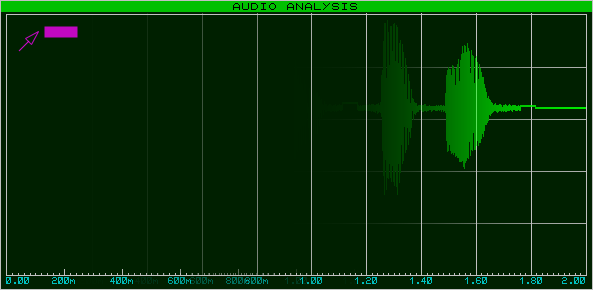
Three virtual instruments let you see what is actually going on. The SPI and I²C Protocol Analysers can sit on the bus as a master, a slave or a passive monitor, decoding traffic down to the bit (start and stop conditions, ACK and NACK, word length, bit order and clock phase), and they can transmit scripted sequences to poke a device under test. The Virtual Terminal gives you a full-duplex RS-232 console for UART work, with the baud rate, data bits, parity, stop bits and handshaking all configurable. Whether you are bringing up a sensor driver, getting a display to talk or just proving a protocol behaves itself, you can see exactly what is on the wire without reaching for a logic probe.
Motor Control & Power Drives
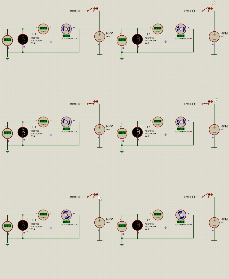
Motor control is one of those topics where the firmware and the physics matter equally, and Proteus models both sides. The motor library covers DC motors with realistic inertia and loading, versions with a built-in position encoder for closed-loop work, bipolar and unipolar steppers, hobby and industrial servos, a three-phase AC induction motor and even a DC generator. Each one is a proper electromechanical model, so it responds to applied voltage with real speed, torque and back-EMF behaviour. You can drive them straight from a microcontroller, or through the same gate drivers and bridge controllers you would use on real hardware, such as the L297 and L298 pair, the DMOS bridges, a range of half-bridge and MOSFET drivers, and parts like the DRV8871 and TB6612FNG.
That means you can build the whole control loop in simulation. Generate PWM on the microcontroller, switch it through an H-bridge, drive the motor, and read the result back: speed from a tachometer, position from the encoder, current through an inline probe. From there it is a short step to closing the loop in firmware with a PID routine and watching it settle. Load a motor up until it stalls and the current climbs just as it would on the bench. Direction control, micro-stepping, soft-start and speed regulation can all be written and debugged with nothing at risk and nothing to burn out.
EDAi and ProPilot: AI-Assisted Design
EDAi is the AI layer built into Proteus, and the thing that sets it apart from a general chatbot is that it can see the live project: the schematic, the firmware and the simulation state, all together. ProPilot is the engineering side of it. Because it knows exactly which peripherals are connected to the microcontroller, and on which pins, it can write firmware that actually fits your circuit: PWM for a motor, an I²C sensor read, a PID loop or a display driver, generated against the real design rather than a textbook example and dropped straight into VSM Studio.
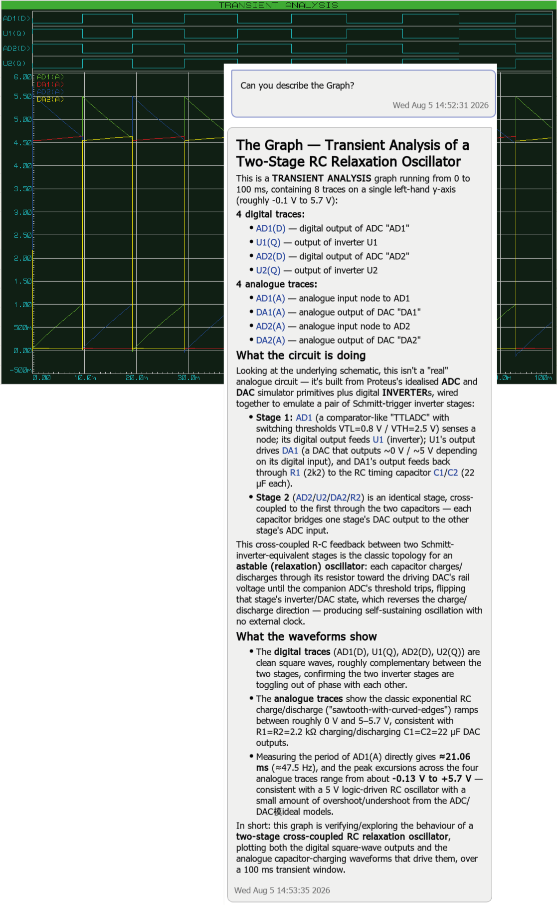
It is just as handy once the simulation is running. ProPilot can place probes where they matter, run the design, read the results back and then tell you what they mean: picking the 3 dB cutoff off a frequency plot, working out the ripple on a power rail, or tying a waveform back to the components causing it. When something is misbehaving, it looks at the circuit in context and suggests likely culprits, from floating inputs and missing pull-ups to a wrong bias point or a misconfigured power path. In commercial work it sits alongside you as a second pair of hands on implementation and debugging. In education it is deliberately more of a guide than an answer machine, nudging students through the reasoning rather than just handing over the result.