Introduction
Controller Area Network, or CAN, is the bus that holds a modern vehicle together. Bosch began work on it in 1983, presented it at the SAE congress in Detroit in 1986, and it went into series production in the Mercedes-Benz S-Class of 1991. A car today carries anywhere from a dozen to well over a hundred electronic control units (ECUs), and most of them talk to each other over CAN. It has spread far beyond cars too, into trucks and agricultural machinery, ships, lifts, factory automation and medical equipment.
If you have already met SPI and I2C (see our overview of communication protocols), the first thing to notice is how differently CAN thinks. There is no master. There are no device addresses. Every frame is broadcast to every node on the bus, and what a frame carries is an identifier that says what the message is, not who it is for. Each node decides for itself which identifiers it is interested in. The bus was designed from the outset to keep working in an electrically hostile environment, to settle contention between nodes without anyone losing data, and to detect corrupted frames reliably.
This article follows one frame from one node onto the wire and explains what every part of it is doing there. Later articles in this series build on it to cover fault finding, security and what actually travels around a car's drivetrain.
Dominant and Recessive
The physical layer most people mean when they say CAN is high-speed CAN, standardised as ISO 11898-2. Two wires, CAN High (CANH) and CAN Low (CANL), form a twisted pair with a 120 ohm termination resistor at each end. A node connects to the pair through a CAN transceiver, which converts the controller's single-ended transmit and receive signals into the differential levels on the bus and back again.
The bus has two states. In the recessive state no node is driving it, the transceivers' bias holds both wires at about 2.5 V, and the voltage difference between them is close to zero. In the dominant state a transceiver pulls CANH up towards 3.5 V and CANL down towards 1.5 V, giving a differential voltage of about 2 V. A receiver simply compares the two wires: a difference above 0.9 V is read as dominant, below 0.5 V as recessive. Noise picked up along the cable appears on both wires more or less equally and cancels in the subtraction, which is how CAN shrugs off the alternator whine and ignition noise of a vehicle.
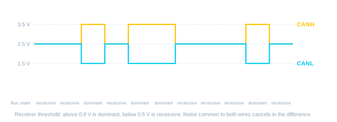
Dominant represents a logical 0 and recessive a logical 1, and the names are chosen because dominant always wins. If any node on the bus drives dominant while the others leave it recessive, the bus is dominant. In logic terms the bus is a wired-AND of every transmitter on it, and nearly everything clever about CAN, from arbitration to acknowledgement to error signalling, is built on that single property.
The controller inside a microcontroller works in logic levels on its TX and RX pins, and it is the transceiver that makes it a CAN node. Any device that can drive a transmit line and read a receive line can sit behind one, which is why CAN controllers exist as stand-alone chips driven over SPI as well as on-chip peripherals.
The Frame, Field by Field
A standard data frame, the kind that carries almost all passenger-car traffic, is built as shown below. It uses an 11-bit identifier and carries up to 8 bytes of data.
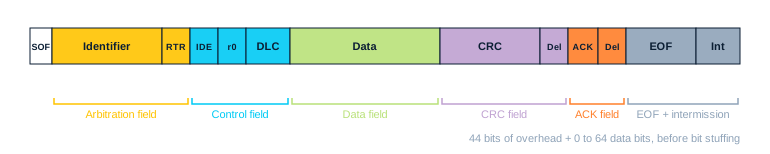
- Start of Frame (SOF): a single dominant bit. The bus was idle and recessive, so this falling edge is what every other node uses to synchronise its bit clock to the transmitter.
- Arbitration field: the 11-bit identifier, most significant bit first, followed by the Remote Transmission Request (RTR) bit. RTR is dominant for a data frame. Sent recessive it marks a remote frame, which asks another node to transmit the data belonging to this identifier. Remote frames are legal but rarely used in modern vehicles.
- Control field: the Identifier Extension (IDE) bit, dominant for a standard frame, a reserved bit (r0) sent dominant, and the four-bit Data Length Code (DLC), which gives the number of data bytes from 0 to 8 (a Classical CAN receiver treats the codes 9 to 15 as 8).
- Data field: 0 to 8 bytes, each sent most significant bit first.
- CRC field: a 15-bit cyclic redundancy check computed over everything from the Start of Frame to the end of the data, followed by a single recessive CRC delimiter. The generator polynomial is x15 + x14 + x10 + x8 + x7 + x4 + x3 + 1, which detects any burst error shorter than 15 bits and, in the bit stream it covers, up to five scattered bit errors.
- ACK field: an acknowledge slot followed by a recessive ACK delimiter. This is the one place in the frame where other nodes get to speak, and it has a section of its own below.
- End of Frame (EOF): seven recessive bits.
After the End of Frame comes a three-bit intermission, also recessive, before any node may begin a new frame. Add it all up and a standard frame wraps 44 bits of overhead around 0 to 64 bits of data. A full eight-byte frame is therefore 108 bits before stuffing, 111 with the intermission, which at 500 kbit/s is a little over 220 microseconds. That overhead is the price of CAN's robustness, and it is why CAN is a control bus rather than a data bus: it moves many small, time-critical messages, not large blocks.
There is also an extended format, introduced with CAN 2.0B in 1991, which stretches the identifier to 29 bits. After the first 11 identifier bits it sends a Substitute Remote Request (SRR) bit and a recessive IDE bit, then the remaining 18 identifier bits, then RTR. Standard and extended frames coexist on the same bus, and a standard data frame always wins arbitration against an extended frame sharing the same first 11 bits: at the twelfth bit the standard frame sends its dominant RTR while the extended frame sends the recessive SRR, which exists precisely as a placeholder to lose that contest. The dominant IDE bit that follows settles the rarer case of a standard remote frame. Extended identifiers dominate in heavy vehicles, where SAE J1939 is built on them, and appear in some diagnostic traffic. Most passenger-car body and powertrain messages use the 11-bit format.
Bit Stuffing
CAN uses Non-Return-to-Zero (NRZ) coding: the bus level simply stays at the bit value for the whole bit time, and there is no transition unless the value changes. That is efficient, but receivers keep their bit clocks aligned to the transmitter by watching edges, and a long run of identical bits gives them nothing to lock onto. The rule that fixes this is bit stuffing. Whenever the transmitter has sent five consecutive bits of the same value, it inserts one bit of the opposite value. Every receiver counts the same way and discards the stuff bit before interpreting what it received.
Stuffing applies from the Start of Frame through to the end of the CRC sequence. The CRC delimiter, the ACK field and the End of Frame have a fixed form and are not stuffed. Two consequences follow. First, a frame's length on the wire depends on its content: the same eight bytes might need no stuff bits at all or, in the worst case, as many as 24, taking the longest possible standard frame to 135 bits including the intermission. Second, six consecutive bits of the same value can never legitimately appear inside the stuffed part of a frame. That makes the pattern of six identical bits a reliable signal that something has gone wrong, and CAN uses exactly that pattern to flag errors, which is where the next article in this series picks up.
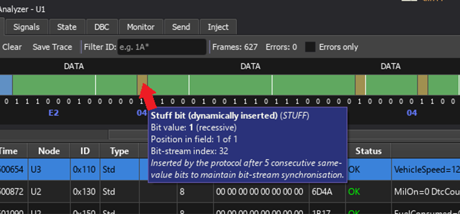 A frame opened bit by bit. The stuff bits are marked; they are on the wire but not part of the message.
Arbitration: Who Wins the Bus
Because there is no master, any node may start transmitting whenever the bus is idle, and two or more nodes will often start in the same bit time. CAN resolves this without either frame being lost. Every transmitter monitors the bus while it sends. During the arbitration field, a node that sends a recessive bit but reads back dominant knows that another node with a dominant bit in that position is transmitting too. It stops at once and becomes a receiver of the winning frame. The winner never notices there was a contest and carries on.
Since dominant is 0, the frame with the lowest identifier value always wins, decided bit by bit from the most significant end. A node that loses simply tries again after the next intermission. In the diagram below node A is sending identifier 0x120 and node B identifier 0x128. The two agree for the first seven identifier bits. On the eighth, A sends a 0 and B sends a 1; B reads the bus, sees dominant, and withdraws. From that bit onwards the bus carries A's frame alone.
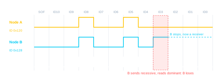
The identifier is therefore a priority as well as a name, and allocating identifiers is a system design decision rather than an afterthought. Engine, braking and steering messages get low numbers; seat heaters and window lifts get high ones. Two further points follow. No two nodes may transmit the same identifier with different content, because both would survive arbitration and the collision would surface later as a bit error. And arbitration only works if a dominant bit driven by one node is seen by every other node within the same bit time, which is the reason bus length limits bit rate, as we will see shortly.
The Acknowledge Slot
During the ACK slot the transmitter sends a recessive bit and listens. Every node that has received the frame so far without error, meaning the CRC it calculated matches the CRC it received, drives that one bit dominant. Every receiving node on the bus does this, not just the ones that want the message. If the transmitter reads back dominant, at least one other node heard the frame correctly. If it reads recessive, nobody did; the transmitter records an acknowledgement error and retransmits.
Note that a dominant ACK means the frame was received intact by someone, not that any particular node acted on it, so acknowledgement is not confirmation of delivery to the intended consumer. Higher-layer protocols add that where it matters. Also, a single node alone on a bus can never be acknowledged. It will retransmit the same frame over and over, its error counter will climb, and it will settle into the error-passive state. A node tested on the bench with nothing else connected does not fail to transmit; it repeats the same frame endlessly, and a listen-only monitor cannot rescue it because a monitor, by definition, does not acknowledge.
From Bytes to Meaning: Signals and the DBC
A frame carries up to eight bytes. What they mean is entirely a matter of agreement between the sender and the receivers; the protocol has no opinion. In the automotive world that agreement is written down in a signal database, most often a DBC file, which describes each message by identifier, name, length and sending node, and each signal within it by start bit, bit length, byte order, sign, scale factor, offset, valid range and unit. The rule for every signal is the same:
physical value = raw value × factor + offset
Take an engine data message with identifier 0x100. Its first 16 bits carry engine speed as an unsigned little-endian value with a factor of 0.25 rpm per bit and no offset. Raw bytes 0x70 0x17 read little-endian as 0x1770, which is 6000, and 6000 times 0.25 is 1500 rpm. The next byte is throttle position at 0.4 percent per bit. Coolant temperature is a single byte with a factor of 1 and an offset of minus 40, so a raw 110 means 70 degrees C. Byte order matters: both little-endian (Intel) and big-endian (Motorola) signals occur in real databases, sometimes within the same message. If those terms are unfamiliar, our article on endianness and bit significance covers them.
An analyser that has the database loaded shows the bus as named signals in engineering units rather than as hex, and that is the moment CAN traffic stops being a stream of bytes and becomes something you can reason about. It is also why a DBC file is treated as confidential by most manufacturers: with it, the entire behaviour of the vehicle network is legible.
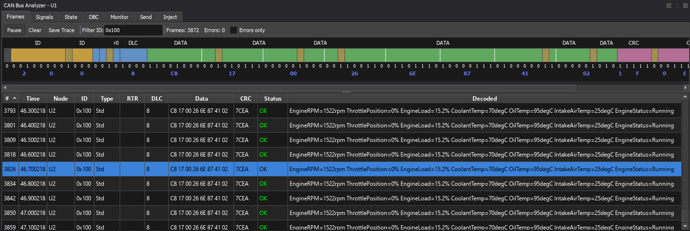 The same frame decoded through a DBC file. Raw bytes become engine speed in rpm, throttle in percent and coolant temperature in degrees.
Bit Rate, Sample Point and Bus Length
Nothing in a CAN frame announces its bit rate. Every node is configured in advance to the same nominal bit time, and receivers synchronise to the transmitter on edges, beginning with the Start of Frame. Each bit time is divided into small time quanta, grouped into four segments: a one-quantum synchronisation segment where an edge is expected, a propagation segment that allows for signal delay across the bus, and two phase segments either side of the sample point, which is where the bus level is actually read. A typical sample point sits 75 to 87.5 percent of the way through the bit. If an edge arrives early or late, the receiver lengthens or shortens the phase segments by up to the synchronisation jump width to pull itself back into step.
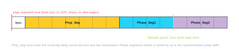
The propagation segment is what ties bit rate to cable length. Arbitration and acknowledgement both rely on one node driving a dominant bit and every other node seeing it, and responding, inside the same bit time. The round trip along the longest path on the bus, through two transceivers, has to fit inside the propagation segment. At 1 Mbit/s that limits a bus to about 40 metres. At 500 kbit/s, the rate most powertrain buses run at, the limit is roughly 100 metres; at 125 kbit/s, common for body electronics, about 500 metres. A car never approaches these lengths, but a tractor with implements, a ship or a factory line easily can.
Classical CAN and CAN FD
Everything above describes Classical CAN. CAN FD (Flexible Data-rate), which Bosch introduced in 2012 and which became part of ISO 11898-1 in 2015, keeps the arbitration mechanism exactly as it is and changes two things once arbitration has been won. The data field can be up to 64 bytes long, and the transmitter may switch to a faster bit rate for the data and CRC phases, typically 2 to 5 Mbit/s, before dropping back to the nominal rate for the acknowledgement. Arbitration itself still has to run at the slower rate for the reason given above.
An FD frame is flagged by a recessive bit in the position where a Classical base frame sent its reserved r0 bit (in the extended format, the first reserved bit). A dominant reserved bit follows, then the Bit Rate Switch bit that says whether the fast phase is in use, then an Error State Indicator that tells the bus whether the sender is error active or error passive. FD frames carry a longer CRC, 17 bits for up to 16 data bytes and 21 bits beyond that, together with a stuff-bit count that closes a weakness in the classical error detection. They have no remote frames. A Classical controller built to the 2015 standard reads that recessive reserved bit as a form error; older controllers accept it, misread what follows and fail with a stuff, CRC or form error soon after. Either way the FD frame is destroyed, so Classical and FD nodes cannot share a bus unless the Classical nodes are FD-tolerant, meaning built to recognise and ignore FD frames.
Summary
One CAN frame, then, is a small piece of engineering. A dominant bit that always beats a recessive one gives a wired-AND bus. An identifier sent most significant bit first turns that into a priority scheme where contention costs nobody any data. Bit stuffing keeps every receiver locked to the transmitter's clock and, as a side effect, reserves a bit pattern for signalling errors. A 15-bit CRC checks the frame, and every node that agrees with it says so in a single shared bit. What the bytes mean is written down outside the protocol, in a database that turns the frame into engine speed and coolant temperature. Once you can see each of those parts happening on the wire, the rest of CAN, faults, security and the messages that run a car, follows naturally.
Everything in this article from the frame upwards can be watched happening on a simulated bus. The Proteus CAN Bus Analyser captures every frame, opens it bit by bit with the stuff bits marked, and decodes it by name from a loaded DBC file. Any Proteus VSM processor can join the bus, either through an on-chip controller or through the MCP2515 and MCP2518FD stand-alone controller models over SPI. The can_analyser sample design is the place to start.
All content Copyright Labcenter Electronics Ltd. 2026. Please acknowledge Labcenter copyright on any translation and provide a link to the source content on www.labcenter.com with any usage.Get our articles in your inbox
Never miss a blog article with our mailchimp emails
Automotive CAN Simulation
A complete vehicle network in software: behavioural car-part models, any Proteus VSM processor as an ECU, and a bus analyser that shows every frame down to the bit.
 Ask An Expert
Have a Question? Ask one of Labcenters' expert technical team directly.