As electronics technologies continued to develop in the late 20th century, it became obvious that there was a need for electronics chips (integrated circuits) to be able to talk and share data with each other; communication protocols were developed to fit the need, and many of these are still staples of the industry today.
Terminology
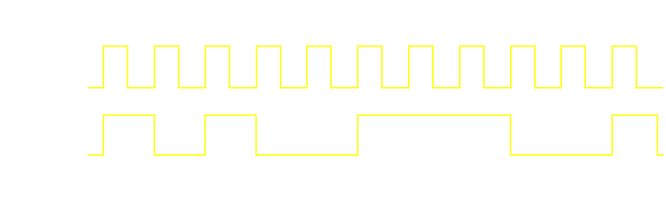
Synchronous protocols have a dedicated clock line, and one or more data lines. The data line is read when the clock line changes from high to low (or vice versa).
 Synchronous Data Transmission.
The speed of the communication is thus defined by the clock line, which dictates exactly when each bit of data on the data line should be read. The clock line is typically controlled by only the master device on the bus, with the slaves only reading the clock line (not driving it).
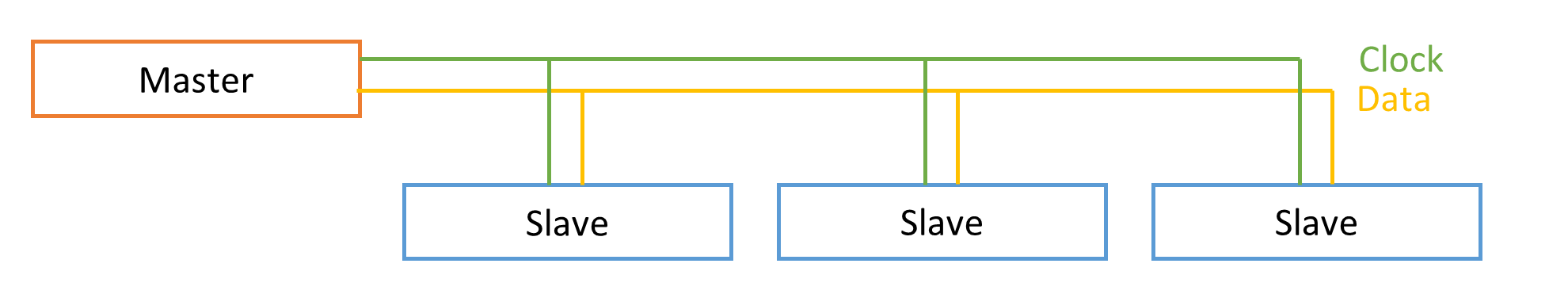 Master Slave Synchronous Transmission.
Asynchronous protocols have no clock line, and so rely on accurate timekeeping on both sides of the communication as well as a previously-agreed-upon communication speed (the baud rate). One less line/wire is needed, but both sides must keep time accurately. Precise crystal oscillators are often used to ensure that the timekeeping and communication speed are accurately measured and maintained (a prerequisite to valid communication with this method).
Full Duplex means that data can be both sent and received at the same time (separate transmit and receive lines/wires), whilst Half Duplex means that data can only either be sent or received at any given time (one line/wire used for both transmit and receive).
UART
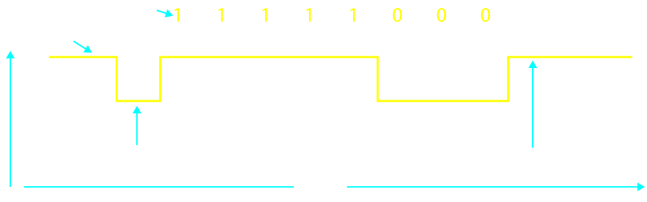
The Universal Asynchronous Receiver and Transmitter was one of the earlies protocols to be developed. Being Asynchronous there is no clock line (although there is a version called USART – Universal Synchronous / Asynchronous Receiver and Transmitter – which does optionally have a clock line), and this is a full duplex protocol. Both sides must be set to the same baud rate (communication speed); with common speeds being 9600, 19200 and 115200 bps (bits-per-second). GPS and GSM modules typically communicate using UART, and there are converter chips for communicating with a computer via UART through USB as well (such as the ubiquitous FT232R). UART used to be common on computers, called the COM or RS232 port, however has subsequently been replaced by USB (although the aforementioned USB-UART converter chips are still widely used, to simulate a COM / TTY port on the computer).
 UART Signal.
Communication starts when the line drops from high to low (the line idles high). This initial drop is called the start bit. After the start bit come the data bits (usually 8), and then a stop bit (high level). If the line is not high when the stop bit is expected then a framing error is declared. 10 bits are thus required for each 8 bits of data transmitted. There can also be a parity (error checking) bit and/or more than one stop bit, however 'no parity and '1 stop bit' is the usual setting. If either side is using an incorrect baud rate (or different parity / stop-bit settings) then garbled data will come through (and errors will be declared).
UART can also implement 'Flow Control' lines (RTS – Ready to Send and CTS Clear to Send), for telling the other side to wait if the receiver is still busy and not yet ready to receive more data; these are used for example by BlueTooth modules where there is perhaps bad signal and data cannot be transmitted over the BlueTooth radio link as fast as what it can be over the wired UART link (as an interesting note, BlueTooth was originally developed to be a wireless UART). For more reliable communication in electronically noisy environments and/or over long distances, UART can be transmitted over a differential pair (see our high speed design article) – such as with RS485/RS422.
SPI
The Serial Peripheral Interface is a synchronous protocol, and as such uses a clock line. Multiple slaves can be connected to the same SPI bus. There is a Clock (SCK) line, a Master-Out-Slave-In (MISO) line (master transmit, slave receive), a Master-In-Slave-Out (MOSI) line (slave transmit, master receive) and one chip select (CS) line per slave. When multiple slaves are connected to the same SPI bus, then the CS lines are used to select which slave is currently active on the bus. The CS line is also used by some peripherals as a start or restart line (to initiate taking a measurement, for example), whereas other times it can simply be permanently tied low (always selected) if the peripheral is the only slave on the bus. SPI is a full-duplex protocol, however there are other configurations such as Dual and Quad SPI where 2 or 4 half-duplex data lines are used to increase throughput (speed).
I2C
I2C is a synchronous half-duplex protocol, using only two lines – clock (SCL) and data (SDA). There can be multiple slaves on an I2C bus, however unlike SPI there are no chip select lines – each device rather has an address by which it is selected (part of the protocol). As with SPI the lines idle high, and there are special transition methods used to signal conditions, such as start (SDA goes low, then SCL) / stop (SCL goes high, then SDA). The slave address is the first byte transmitted after the start condition, together with a read / write bit (whether the master wants to read from or write to the slave).
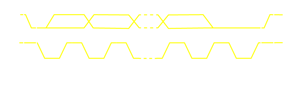 I2C Packet Transmission.
In order to avoid bus contentions (where the master and a slave both try to drive a line to a different level, creating a short-circuit), and as part of the protocol, the master / slave are only ever allowed to drive the lines low, with the lines being driven high by external weak pull-up resistors when the lines are released. After each byte of data transmitted, the receiver (could be either the master or the slave) must hold the SDA line low for 1 SCL cycle, to acknowledge that it received the transmitted byte correctly.
More Protocols
UART, SPI and I2C are the most common protocols in the embedded world, and almost all microcontrollers include built-in peripherals for processing these protocols. With the built-in peripherals, and software driver libraries available, it is usually not necessary to understand the nitty-gritty of each protocol – it can be very helpful however if there is a problem, and debugging with an oscilloscope becomes necessary!
USB
USB (Universal Serial Bus) was invented to replace UART on laptop/desktop computers. USB is a complex synchronous protocol, with many device classes, and requries a book to explain properly. For many embedded developers, using the built-in peripherals and available software driver libraries is enough to get their project working without understanding USB in-depth. The Proteus USB Analyser can however be an extremely useful tool for learning about the nitty-gritty of the USB protocol and/or doing in-depth development with USB. USB communicates over a differential pair.
Take a primer on high speed design by reading our recent blog post.CAN
CAN (Controller Area Network) is a synchronous protocol developed for high-reliability use in vehicles, and which has a message priority function built-in. Data is transmitted over a differential pair (CANH – CAN High, and CANL – CAN Low). Like I2C, CAN idles in an undriven state – communication is started by one of the devices on the bus starting to drive it. As part of the protocol, when transmission is started then messages with a higher-priority-ID will drive the line when other devices are allowing it to idle, which will let the devices which are trying to transmit the lower-priority message know that they should back off until after the higher-priorty message has been transmitted. There are different versions of CAN, with different message frame sizes and baud rates. There are also sub-protocols built on top of CAN, such as the J1939 used in heavy / industrial vehicles. We won’t deep-dive into the details of the CAN protocol (including its different versions and sub-protocols) in this article.
Ethernet
Ethernet is a communication protocol developed for computer networking, usually also working over differential pairs. As with USB, Ethernet is a complex technology which we will not tackle in-depth in this article. With the built-in or external microcontroller peripherals available, as well as software driver libraries, the typical developer can implement ethernet in their project without getting into the details.
Simulation and Debugging
Proteus includes hundreds of microcontrollers available for simulation, which feature communication peripherals handling the protocols listed here. Proteus also includes virtual instruments for studying and debugging the protocols; such as the Virtual Terminal (UART), SPI Debugger, I2C Debugger and Oscilloscope. Find out more here.
All content Copyright Labcenter Electronics Ltd. 2026. Please acknowledge Labcenter copyright on any translation and provide a link to the source content on www.labcenter.com with any usage.Get our articles in your inbox
Never miss a blog article with our mailchimp emails
Advanced Simulation
Learn more about our built in graphing and advanced simulation features. Harness the mixed-mode simulation engine in Proteus to quickly test your analog or digital circuitry directly on the schematic.
 Ask An Expert
Have a Question? Ask one of Labcenters' expert technical team directly.