Introduction
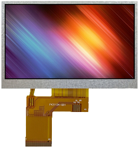
TFT (thin-film-transistor) displays are ubiquitous nowadays, and are finding uses in more and more applications. Not too long ago an LCD (liquid crystal display) or GLCD (graphic LCD) would suffice for most embedded applications, but now user demands and expectations are higher and electronic engineers have to keep up by incorporating more complex technologies into their products in order to remain competitive. Display technology is complex and this article does not aim to delve into the deep details of every aspect thereof, but rather to provide a relatively high-level practical overview.
How TFTs Work
At the risk of stating the obvious, TFT displays are comprised of a grid of pixels which are used to display an image.
 Pixels in a grid formation.
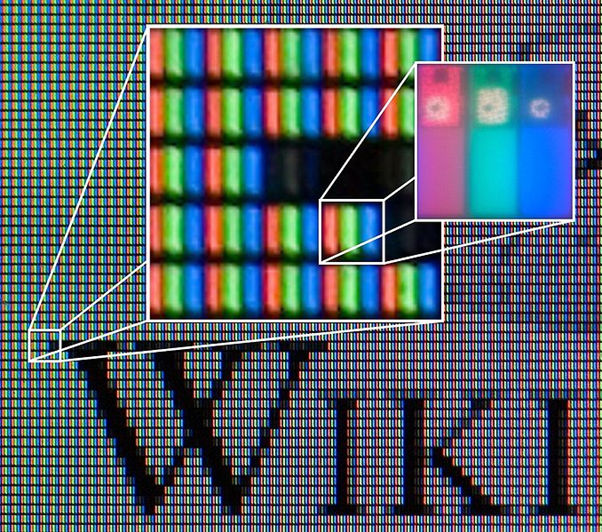
This is the same as GLCDs, except that TFTs are colour rather than monochrome. In order to produce a colour image, each pixel consists of red, green and blue sub-pixels (the primary colours of light); the brightness of each sub-pixel can be individually controlled, and when the sub-pixels are viewed from far-enough-away then they combine to look like a single pixel of a given colour. With TFTs, the transistors controlling the pixels are embedded within the pixels themselves (rather than the transistors existing in an external control circuit), and this enables fast refresh rates and precise brightness control amongst other advantages (disadvantages are higher cost and power consumption).
Behind the TFT matrix is a backlight, and each sub-pixel acts as a sort of window-blind to either allow light through or block it. The “window-blind” consists of liquid crystal sandwiched between two orthogonal polarising filters, with the liquid crystal either assisting-the-light-with or blocking-the-light-from passing through the filters, depending on the voltage applied across it. Each sub-pixel also has a colour filter on top of it, which gives it the red, green or blue colour.
Driving TFT
The matrix of pixels (sub-pixels) in the TFT are controlled by a line (wire) for each row and each column. Inside the TFT is a controller chip (e.g. ILI6480, HX8257A, ILI9341) which is connected on its outputs to each row and each column of the pixel (sub-pixel) matrix. Because TFTs are “active matrix” (as opposed to “passive matrix”), the pixels must be constantly refreshed in order to maintain the display (pixels in a “passive matrix” display maintain their setting until set otherwise).
Depending on the driver chip, it will have one or more input interfaces.
Parallel RGB Interface
Perhaps one of the most common input interfaces in embedded applications is the parallel RGB interface. An example pinout for a 40-pin Parallel RGB Interface is below:
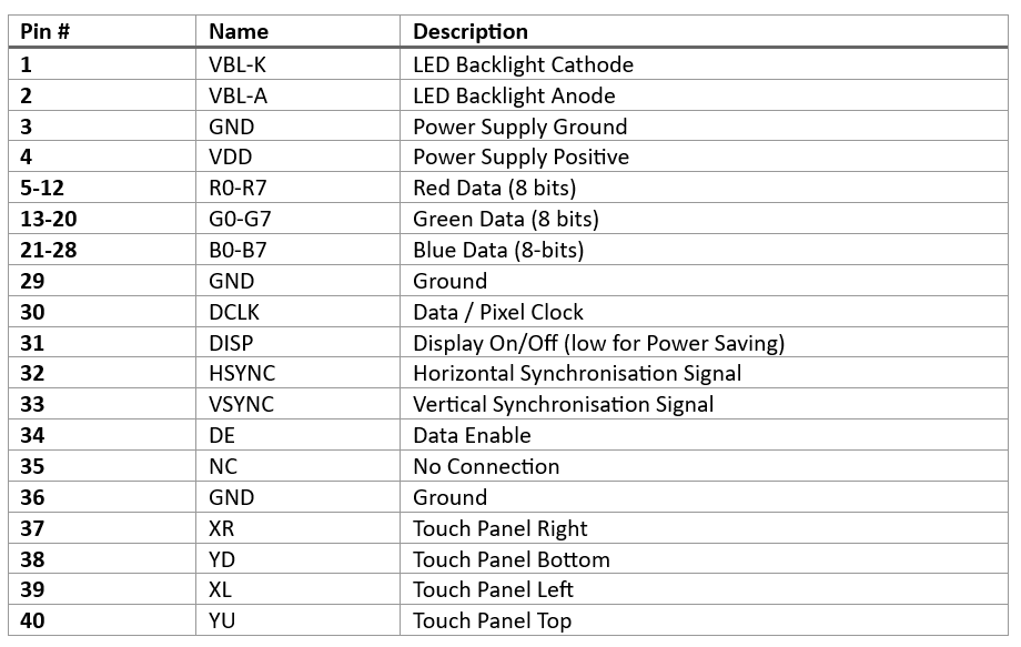
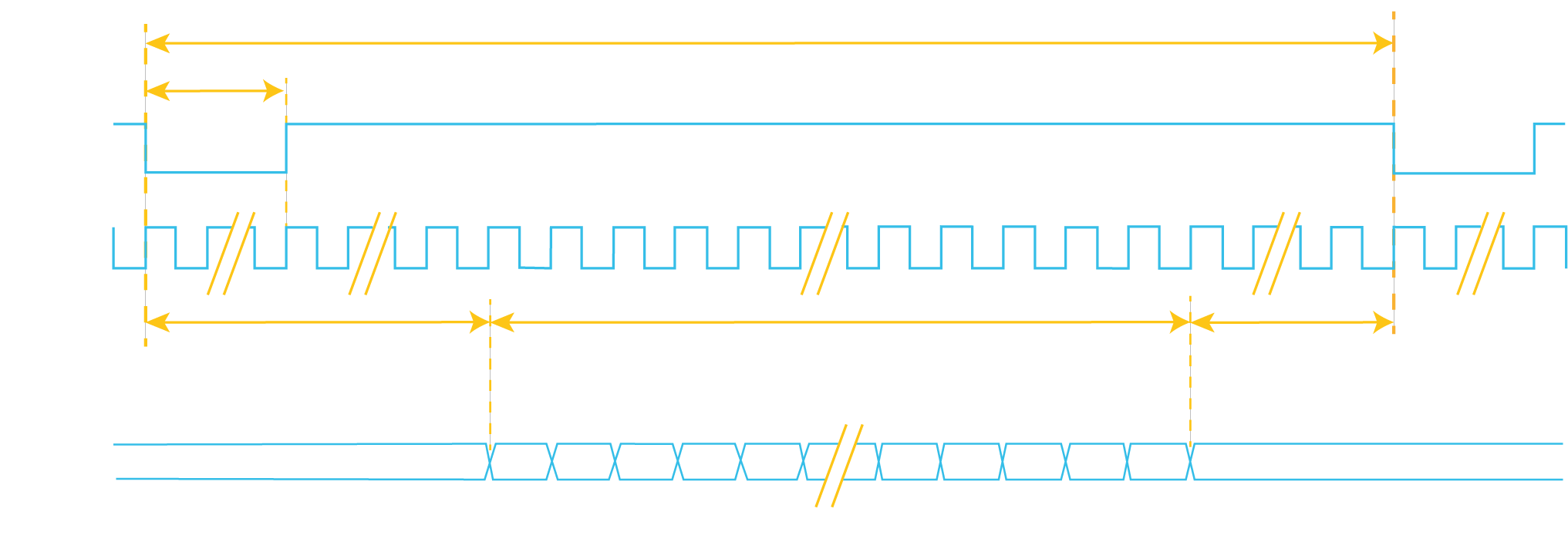
Each pixel has 8-bits of data for each of the red, green and blue channels (total 24-bits). A Pixel Clock is used to clock the data in; a Vertical Synchronisation signal is used to indicate the start/end of a complete frame; and a Horizontal synchronisation signal is used to indicate the start/end of each line.
The speed (frequency) of the Pixel Clock will determine how long it takes to draw each frame, and therefore determine the frame rate.
The Horizontal and Vertical Synchronisation signals will normally have pulses of much longer duration than the Pixel Clock, creating so-called “front and back porches” for both the HSYNC and VSYNC lines.
Valid ranges of values for each of these parameters are normally included in the display datasheet.
The interface needs to be constantly driven and refreshed, or the display will go blank.
The parallel RGB data for the display may in turn be generated by another driver chip, such as the SSD1963 (separate parallel input interface) or FT8xx (SPI/I2C interface) series of display controllers; or some MCUs / MPUs have peripherals capable of directly outputting the parallel RGB data (and associated clock / sync signals).
SPI/I2C/UART Interface
Some driver chips (e.g. ILI9341) have a serial communications interface (such as SPI/I2C/UART) which can be used to control the display. The protocol varies from chip to chip and there are usually accompanying software libraries available for drawing text / graphics / etc onto the display. Because the maximum speed/throughput of these serial interfaces is relatively slow, it can take some time to update the display and they are better suited for applications where only small sections of the screen need to be updated regularly (e.g. the text of a sensor reading); they are not well suited for applications where the content of large regions of the screen must change quickly (such as video playback).
MIPI-DSI
The “Mobile Industry Processor Interface” Alliance “Display Serial Interface” is a screen communication interface based on differential-pair signalling (for more information on differential pairs please see our “high speed design” article). There is one “clock” differential-pair, and then one or more “data” diff-pairs. Because differential-pairs are used, clock speeds can be in the GHz range, and there is low EMI and high immunity to interference (see our EMI/EMC article for more information on these topics). Because of the high speed as well as the possibility to adding more data lanes to increase data throughput, MIPI-DSI is well suited for larger high-resolution displays where the parallel RGB interface throughput is no longer sufficient (above approximately 1024x768). MIPI-DSI is used on the popular RaspberryPi.
Integration
When starting a project which will incorporate a TFT, then a number of factors should be considered such as:
- Size and resolution of display required.
- Refresh rate / throughput required.
- Microcontroller / microprocessor used and its available peripherals and processing power / speed.
More powerful MCUs/MPUs will often have peripherals capable of driving TFTs directly. If fast refresh rates are not required or only a small region of the screen will be updated regularly then a display with an SPI/I2C/UART interface may suffice. For smaller, less powerful processors there are various industry players available which offer simplified display solutions where an intermediate dedicated graphics processor chip drives the display; such as 4D Systems / Nextion / FT8xx EVE / etc.
Proteus includes an ILI9341 display model, which can be used to experiment with a TFT display under simulation.
Get our articles in your inbox
Never miss a blog article with our mailchimp emails
Advanced Simulation
Learn more about our built in graphing and advanced simulation features. Harness the mixed-mode simulation engine in Proteus to quickly test your analogue or digital circuitry directly on the schematic.
 Ask An Expert
Have a Question? Ask one of Labcenters' expert technical team directly.