Introduction
CAN was designed on the assumption that things would go wrong. A vehicle bus spends years next to an alternator, running through connectors that corrode and harnesses that chafe, between ECUs that occasionally crash and are occasionally replaced by a unit programmed for a different model. So the protocol carries a complete fault-handling system of its own. Every node keeps score of its own behaviour, misbehaving nodes are progressively silenced, and a node that has taken itself off the bus has a defined route back. This is one of the things that makes CAN worth studying rather than simply using.
It also makes fault-finding a skill in its own right, and an awkward one to learn, because none of this machinery is visible on a healthy bus. You cannot learn to read an error frame, watch a node go bus-off or recognise a babbling node from a working car, since a working car never shows you any of it. This article sets out the faults CAN itself defines, the larger family of faults that come from the nodes rather than the protocol, and a method for working back from what a bus analyser shows to what has actually gone wrong. It assumes the frame structure covered in Anatomy of a CAN Transmission.
What a Healthy Bus Looks Like
Every fault below is a departure from normal, so the first job is to know what normal looks like on the bus in front of you. Almost all traffic on a vehicle bus is periodic. Each ECU transmits each of its messages on a fixed schedule: 10 or 20 ms for fast signals such as wheel speeds and engine speed, 100 ms for slower engine data such as temperatures, 500 ms or a second for status and body messages. An analyser shows this directly. Each identifier reappears with a steady period, the frame count per second for each identifier is constant, and the bus load, the fraction of time the bus is actually busy, sits at a steady figure. Designers usually keep that figure well under the maximum, often below 60 percent, so that low-priority messages still get through on time.
For any bus you work on, learn which identifiers are present, what period each one has, and what the error counters read, which on a healthy bus is zero or close to it. Everything that follows is a change in one of those three.
The Five Protocol Errors
CAN defines exactly five error conditions, and between them the transmitter and the receivers check for all five on every frame. Bit errors are caught by whichever node is driving the bus at the time, which is mostly the transmitter; acknowledgement errors by the transmitter alone; and every receiver checks for stuff, form and CRC errors whether or not it is interested in the message. Detection is a shared duty, not the consumer's private problem.
- Bit error. A transmitter reads back a different level from the one it sent. The exceptions are deliberate: sending recessive and reading dominant during the arbitration field is losing arbitration, not an error; reading dominant in the ACK slot is an acknowledgement; and a node sending a passive error flag expects to be overwritten. Anywhere else, a mismatch means another node is driving the bus when it should not be, or the wire is at fault.
- Stuff error. Any node sees six consecutive bits of the same level in the stuffed part of the frame, from the Start of Frame to the end of the CRC sequence (the CRC delimiter is not stuffed). A valid frame can never contain that pattern.
- Form error. A bit that the frame format requires to be recessive, in the CRC delimiter, ACK delimiter, End of Frame or an error or overload delimiter, arrives dominant. The one exception is a dominant last bit of the End of Frame, which receivers treat as an overload condition rather than an error.
- CRC error. A receiver's own calculation of the 15-bit CRC does not match the one it received.
- Acknowledgement error. The transmitter reads recessive in the ACK slot: no node on the bus received the frame correctly.
Detecting an error is only half of the mechanism. The node that detects one immediately transmits an error flag of six consecutive dominant bits, starting at the very next bit, or, for a CRC error, at the bit after the ACK delimiter. Six dominant bits are themselves a stuffing violation, so every other node now detects an error of its own, a stuff error in most cases, a form error if the flag lands in a fixed-form field, a bit error for the transmitter whose frame is being overwritten, and sends a flag of its own. The flags overlap, the bus sees somewhere between six and twelve dominant bits, and each node then sends an error delimiter of eight recessive bits. The frame has been destroyed for everyone at the same moment, which is the point: CAN is designed so that either every node accepts a frame or none does. After the usual intermission the original transmitter simply sends the frame again.
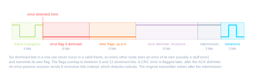
Automatic retransmission is why a single burst of interference costs a few hundred microseconds and nothing more. It is also why a persistent fault could, in principle, lock a bus up: a node retransmitting a frame that fails every time would take the bus for ever. Preventing that is the job of the error counters.
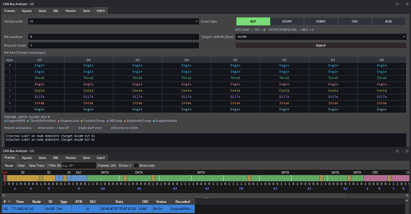 An error injected against one node. The frame is marked in the capture and the node's transmit error counter steps up by eight.
Error Counters and the Three States
Fault confinement is the part of CAN that stops a faulty node taking the bus down with it. Every controller keeps two counters, a transmit error counter (TEC) and a receive error counter (REC), and the rules that move them are deliberately asymmetric. When a node is transmitting a frame and has to send an error flag, its TEC goes up by 8, with two deliberate exceptions: an error-passive transmitter whose only problem is the lack of an acknowledgement stops counting, so a node alone on a bus parks at error passive rather than ejecting itself, and a stuff error during arbitration does not count either. When a node detects an error in a frame it is receiving, its REC goes up by 1, and by a further 8 if, having sent its flag, it immediately sees a dominant bit, since that means it was the only node to see a problem and the fault is probably its own. Every successful transmission takes 1 off TEC and every successful reception takes 1 off REC, except that a REC above 127 drops straight back to between 119 and 127 on the first good reception. Errors cost eight and successes earn one, so a transmitter breaks even at one failed frame for every eight good ones; anything worse and its counter climbs.
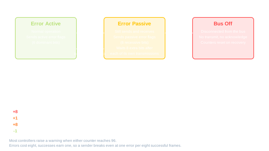
Three states follow from the counters. With both below 128 a node is error active, which is normal: it transmits, receives and signals errors with the six-dominant-bit active flag. Once either counter exceeds 127 the node is error passive. It still sends and receives, but its complaints are no longer trusted: it signals errors with a passive flag of six recessive bits, which disturbs nobody when the node is receiving (a passive transmitter that stops mid-frame still destroys its own frame), and it must wait eight extra bit times after each of its own transmissions before starting another, so that healthy nodes get the bus first. If TEC exceeds 255 the node goes bus-off. Note that only the transmit counter can do that. A node that receives badly is parked at error passive for as long as its receptions keep failing; a node that transmits badly is removed. That is the intent: the node most likely to be doing the damage is the one taking the bus, and it is the one silenced.
The counters are also the earliest warning you have. Most controllers raise a warning interrupt when either counter reaches 96, long before anything is silenced, and a bus whose counters sit at 20 or 30 and never fall back to zero has a problem that has not yet become a fault. On an analyser that shows per-node counters, a healthy bus reads zeros. Anything else is a lead.
Bus-Off and Recovery
A bus-off node neither transmits nor acknowledges. From the bus's point of view it has been unplugged; it has no vote. To come back it must observe 128 occurrences of 11 consecutive recessive bits. The tail of every frame, from the ACK delimiter through the End of Frame and intermission, is exactly 11 recessive bits, so on a saturated bus that means about 128 frames. On a normally loaded bus the idle gaps between frames count too, and recovery takes a few milliseconds; on an idle bus it is exactly 1,408 bit times, under 3 ms at 500 kbit/s.
What happens at the end of that period depends on the controller. Some rejoin automatically with both counters reset to zero. Others stop and wait for the host firmware to re-initialise them, and many offer both behaviours as a configuration bit. The second option exists for a good reason: a node that has just been thrown off the bus for corrupting traffic should probably not come straight back and do it again. The firmware decision matters more than it looks. A node that rejoins automatically and immediately fails again cycles between bus-off and error active indefinitely, injecting a burst of error frames every few milliseconds; a node that never rejoins is dead until someone turns the ignition off and on. Neither is what you want. A recovery that is counted, backed off and logged is.
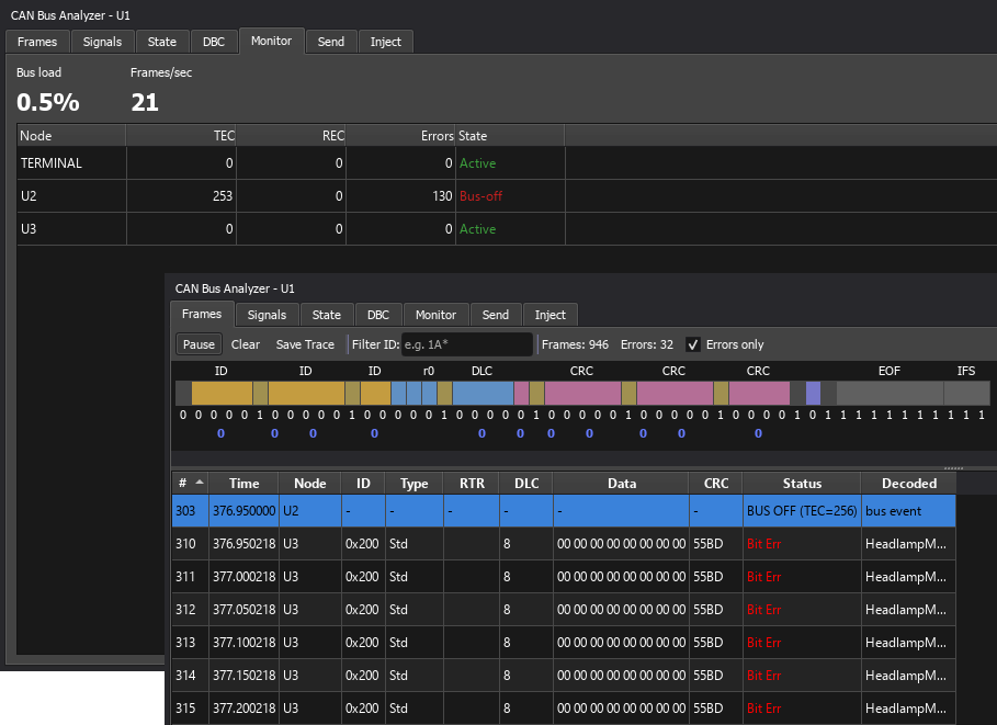 One node driven to bus-off. Its counter passes 255, its identifiers stop, and the event appears in the frame list alongside its later recovery.
On an analyser a node going bus-off has a recognisable shape: a burst of error frames all tied to one sender, its TEC climbing in steps of eight, then silence from every identifier that node owns, and, if it recovers, their reappearance some time later. Learn that shape once and you will recognise it for the rest of your career.
When the Protocol Is Fine but the Node Isn't
The five errors above are the faults CAN itself can detect. A much larger class of faults never trips any of them. The frames are perfectly formed, arrive with valid CRCs and are acknowledged by everyone, and something is still wrong. These are faults of the node rather than of the protocol, and they are the ones that fill a workshop's day. Each has a characteristic signature on the analyser.
- The silent node. Powered and acknowledging other traffic, but sending nothing of its own. Its identifiers vanish from the bus and nothing else changes. Typically the application has crashed or the task that reads the sensor has stopped.
- The dead node. No power at all: no frames and no acknowledgements. On a busy bus it looks exactly like the silent node. On a two-node segment the difference is stark, because the survivor now collects an acknowledgement error on every frame, climbs to error passive within sixteen attempts, and sits there retransmitting the same frame indefinitely.
- The intermittent node. Comes and goes on a timescale of hundreds of milliseconds to seconds. Consumers time out and recover repeatedly, and the current-fault flag on their stored codes sets and clears with it. A connector, a chafed harness or a marginal supply.
- The frozen node. Transmits on schedule and the payload never changes. This is the hardest to see, because cadence and CRC are both fine; only the values give it away. A stuck sensor, or a task that has latched its last good reading.
- The off-rate node. The right frames at the wrong period. A scheduler fault or a task overrun. Consumers with tight timeouts trip; the rest keep working on data that is older than they think.
- The babbling node. Transmits far faster than its schedule. Bus load jumps, and every identifier with a lower priority than the babbler's arrives late or not at all, because it loses every arbitration to it. It is the classic CAN failure mode, and the babbler never reports itself: its victims do.
- The garbling node. Valid frames carrying nonsense. The values fail range and rate-of-change checks and the decoded signals are physically impossible. Corrupted memory, or a new firmware build with the wrong scaling.
- The wrong-identifier node. A real message transmitted under the wrong identifier, from a misconfigured or cloned ECU. The expected identifier disappears and an unknown one appears. If the wrong identifier belongs to another node, two transmitters now share one identifier. When both happen to start a frame in the same bit time with different content, the one sending recessive at the first differing bit takes a bit error, the other detects the resulting error flag, and both counters step up by eight; the rest of the time their frames simply interleave, and only the doubled rate and the alternating payload give the game away.
Few of these produce any protocol error at all. Only the dead node on a small segment and the occasional wrong-identifier collision touch the error counters. The rest are invisible to CAN's own machinery and visible only to someone, or something, that knows what the traffic ought to look like.
Reading the Symptoms
With the catalogue in hand, fault-finding becomes a method rather than a hunt. Work in this order. First cadence: which identifiers are present, and at what period, compared with normal. Second content: decode what is present and check the values against their range and against each other. Third counters: whose error counters have moved, and when they started moving. Fourth isolate: decide whether the symptom belongs to one message, one node or the whole bus. One caution about the third step: the counters live inside each controller and are not on the wire. A simulator can show every node's counters directly; on a real bus you infer them from which frames the error flags land on, and read each ECU's own error status through a diagnostic request.
The three examples below use the Proteus Automotive CAN simulation and its CAN Bus Analyser, with a fault set on one of the behavioural car-part nodes. The principles are identical in any other analyser; only the window furniture differs.
A silent node. The engine ECU has been muted. In the frame list the ENGINE_DATA identifier has simply stopped while every other identifier keeps its period, no error frames appear and the counters do not move. Within a second or two the instrument cluster reports lost communication and the gearbox controller logs U0100. Cadence has changed for one identifier and nothing else has, which places the fault in the application or the power supply of that one node.
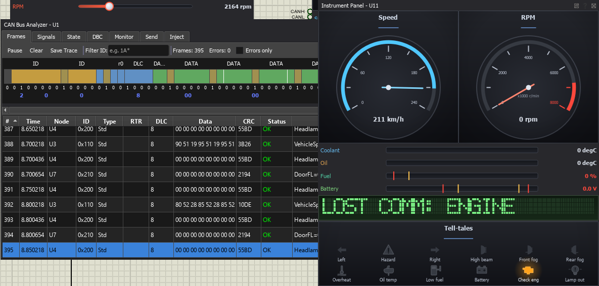 The silent node. One identifier gone, every other period unchanged, counters flat. The cluster has already noticed.
A babbling node. A body node has been set to flood. The bus load figure jumps, the frames-per-second column shows one identifier running far above its schedule, and the periods of every lower-priority identifier stretch as they lose arbitration to it. The counters still do not move, because every one of the babbler's frames is perfectly valid. The babbler never reports itself; the per-identifier rate is what points at it.
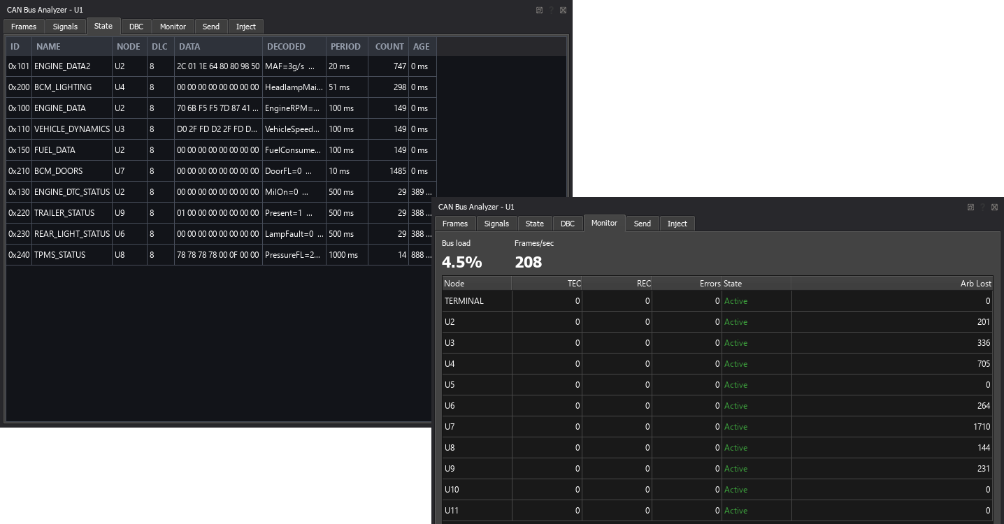 The babbling node. Bus load up, one identifier far above its schedule, lower-priority messages late.
A frozen node. The engine ECU is transmitting again, but with its payload stuck. ENGINE_DATA arrives on schedule with a valid CRC and is acknowledged by everyone, and the decoded engine speed has not changed in several seconds while the throttle is being moved. Cadence and counters are normal; only the content is wrong, which is the signature of the application layer.
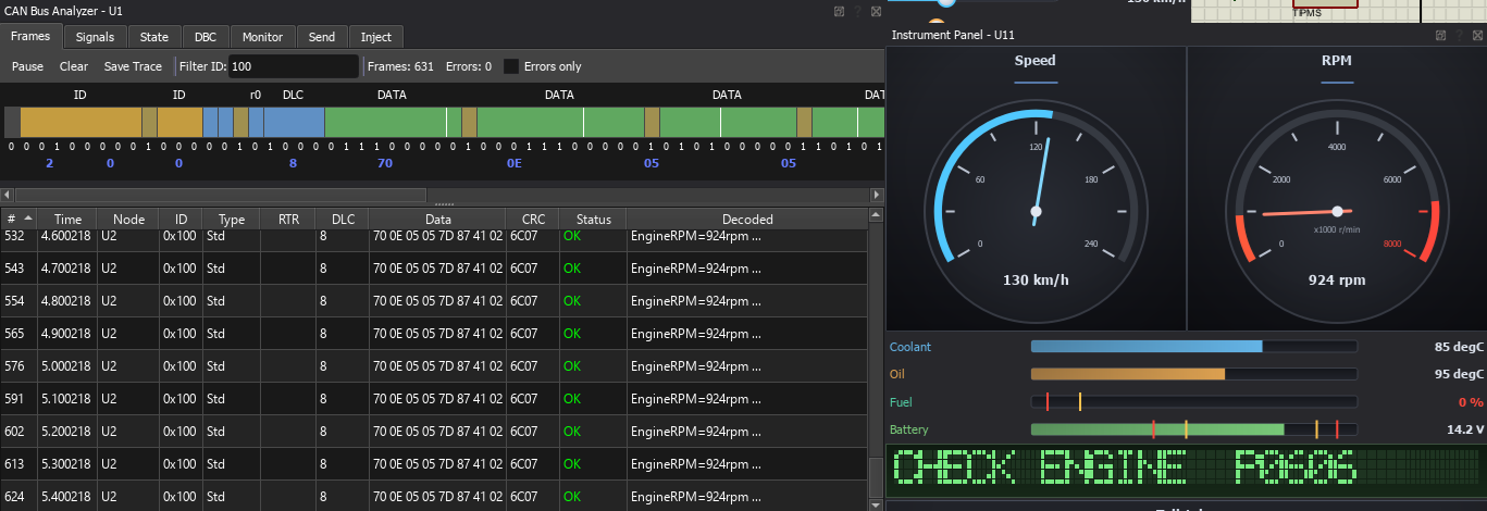 The frozen node. On time, valid, acknowledged, and not changing.
The same reading extends to the rest of the catalogue. A wrong identifier shows as an unknown identifier appearing while a known one disappears, with the payload of the newcomer matching the missing message. An off-rate node shows as a period that does not match the specification, with the values otherwise fine. Two nodes on one identifier show as a doubled rate with alternating payloads and the occasional bit error on both. An intermittent node shows as an identifier that comes and goes, and as stored codes that are not currently failing. A physical-layer fault shows as errors landing on frames from many senders at once; on a real high-speed bus, with the power off, the resistance across CANH and CANL should read about 60 ohms, two 120 ohm terminators in parallel, and 120 means one terminator is missing.
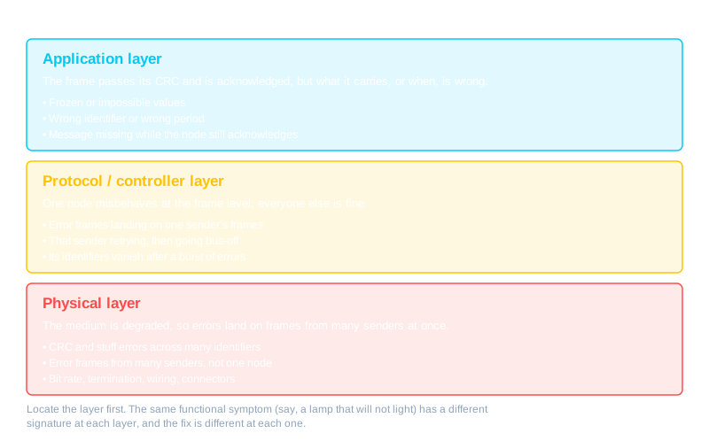
The last step is to place the fault in a layer, because the same functional symptom, a lamp that will not light, say, has a different signature at each layer and a different fix at each one. Errors scattered across many senders point below the protocol, at the wiring, the termination or a bit-rate mismatch. Errors confined to one sender point at that node's controller or transceiver. Clean frames carrying wrong content point above the protocol, at the application.
What the Vehicle Does About It
An ECU that depends on a message keeps a timeout for it, anywhere from a few tens of milliseconds for a fast chassis signal to a couple of seconds for a slow status message. When the timeout expires the ECU does two things. It substitutes a safe default, so a gauge drops to zero or shows a warning, a lamp goes to a defined state, a gearbox holds a fixed ratio. And it logs a diagnostic trouble code (DTC). Network faults have their own family of codes, the U series: U0100 is lost communication with the engine control module, U0140 lost communication with the body control module, U0073 is the code a module logs about itself when it has been bus-off.
Every consumer logs its own code. When the engine ECU falls silent, the gearbox controller, the instrument cluster and the braking system each record U0100 independently. That is why one dead module fills a scan tool with codes from all over the car, and it is also why the pattern is so useful: the module everyone has lost is the one to look at, and a module reporting U0073 is telling you it was thrown off the bus itself. Stored codes persist. They survive the source coming back and are removed only when a scan tool clears them or when they age out after a set number of fault-free cycles: 40 warm-up cycles for emissions codes under OBD-II, a manufacturer-chosen count for the rest. Each code also carries a status: whether the fault is present right now as well as whether it has been stored. That status is what separates an intermittent fault from a dead node. A stored code that is not currently failing, often with an occurrence counter climbing, says the fault comes and goes; a code that is stored and still failing says the node is gone.
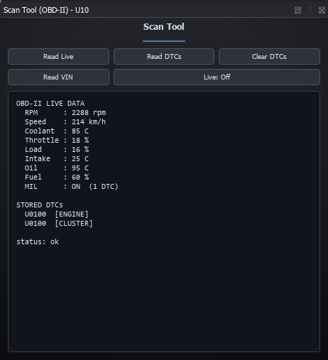 The engine ECU has been silenced. Three other modules have each logged U0100, and the pattern points straight at the missing node.
Writing Firmware That Survives the Bus
Everything above has a mirror image in the firmware of a node that is meant to keep working while the bus around it misbehaves. Most of it is not difficult; it is a matter of deciding in advance rather than discovering in the field.
- Time out every message you consume, and decide the substitute value before you write the first line of the control loop. A missing frame is a normal event, not an exception.
- Check plausibility, both range and rate of change. A wheel speed that goes from 30 to 200 km/h in one 10 ms frame is a fault, not a reading, and it should be treated as one.
- Put an alive counter and a checksum in the payload of anything that matters. A rolling counter and a one-byte checksum, in the style of the AUTOSAR end-to-end protection profiles, catch frozen senders and corruption anywhere in the transmit path, which CAN's own CRC cannot, because the CRC only proves the frame arrived as sent. Wrong values produced by the application itself are a job for the plausibility checks above.
- Handle bus-off deliberately. Count the events, back off between attempts, log the condition and stop after a limit. Do not let the controller cycle.
- Never block on transmit. When the bus is down, a full transmit buffer must not stall the control loop. Overwrite stale data or drop it, and keep the outputs safe.
- Read the error counters and act on the warning limit. A node that notices its own counters rising can degrade gracefully before the bus does it for it.
- Choose identifiers by consequence. Under load, arbitration decides what gets through, so the identifier allocation is a safety decision, not an administrative one.
- Do not act on a single frame for anything safety-relevant. Two consecutive consistent frames cost one period of latency and remove a whole class of glitches.
Summary
CAN watches itself. Five error conditions are checked on every frame, a detection by any error-active node destroys the frame for everyone, and automatic retransmission makes a single fault cost almost nothing. Two counters per node, moving up by eight and down by one, turn a persistent fault into progressive silence: error active, error passive, bus-off, and a defined way back. Beyond that boundary lies the larger world of faults the protocol cannot see, where the frames are perfect and the node behind them is not, and where the analyser's job is to show you cadence, content and counters so that you can place the fault in a layer and name it. The next article turns from faults that happen by accident to the ones that happen on purpose.
All of this can be practised on a simulated vehicle bus. The Proteus CAN Bus Analyser injects any of the five protocol errors against a chosen node from its Inject tab and shows every node's TEC, REC and error state as they respond, with bus-off and recovery recorded as events in the frame list. Each behavioural car-part model accepts a FAULT_MODULE property covering the node faults described here, from silent and frozen through to babbling and wrong identifier, and the Scan Tool model reads the trouble codes the rest of the network logs in response. The bus_off_auto and diagnostics sample designs are the place to start.
All content Copyright Labcenter Electronics Ltd. 2026. Please acknowledge Labcenter copyright on any translation and provide a link to the source content on www.labcenter.com with any usage.Get our articles in your inbox
Never miss a blog article with our mailchimp emails
Automotive CAN Simulation
A complete vehicle network in software: behavioural car-part models, any Proteus VSM processor as an ECU, and fault injection from a single bit error through to a node driven bus-off.
 Ask An Expert
Have a Question? Ask one of Labcenters' expert technical team directly.